Toyota Yaris: Wiper / Washer / Wiper And Washer System
Toyota Yaris XP210 (2020-2026) Reapir and Service Manual / Vehicle Exterior / Wiper / Washer / Wiper And Washer System
- Precaution
- Parts Location
- System Diagram
- System Description
- How To Proceed With Troubleshooting
- Customize Parameters
- Operation Check
- Utility
- Problem Symptoms Table
- Terminals Of Ecu
- Dtc Check / Clear
- Data List / Active Test
- Diagnostic Trouble Code Chart
- Humidity/Rain Sensor Missing Message (B127987)
- Rain Sensor Malfunction (B1400)
- Wiper Module Missing Message (B235787)
- Front Wiper Motor Circuit
- Wiper and Washer Switch Circuit
- Washer Motor Circuit
 Washer Nozzle
ComponentsCOMPONENTS ILLUSTRATION
*1 WASHER NOZZLE SUB-ASSEMBLY - - ● Non-reusable part - - On-vehicle InspectionON-VEHICLE INSPECTION PROCEDURE 1...
 Precaution
PRECAUTION PRECAUTION FOR WASHER NOZZLE ADJUSTMENT (a) Do not clean or adjust the washer nozzle with a safety pin, etc. because: (1) The washer nozzle tip is made of resin and may be damaged...
Other information:
Toyota Yaris XP210 (2020-2026) Owner's Manual: Light Bulbs
Front With Halogen Headlights Headlights (Low/High beam)/Daytime running lights Front side-marker lights Overhead lights/Map lights Side turn signal lights (if equipped) Front turn signal lights/Parking lights Fog lights (if equipped) With LED Headlights Headlights (High beam) Headlights (Low beam) Front side-marker lights Overhead lights/Map lights Side turn signal lights (if equipped) Front turn signal lights/Parking lights Daytime running light/Parking light Fog lights Rear 4-Door Trunk light High-mount brake lights License plate lights Reverse lights Rear turn signal lights Brake lights/Taillights/Rear side-marker lights 5-Door High-mount brake light License plate lights Reverse lights Rear turn signal lights Brake lights/Tail lights Rear side-marker lights Luggage compartment light To replace the bulb, contact your Toyota dealer...
Toyota Yaris XP210 (2020-2026) Reapir and Service Manual: Fail-safe Chart
FAIL-SAFE CHART If any of the following DTCs are stored, the engine stop and start ECU enters fail-safe mode to preserve vehicle operability. DTC Component Fail-safe Operation Fail-safe Deactivation Condition P033562 Open in engine speed signal circuit Stop and start control is prohibited Engine is automatically restarted if a DTC is stored while the engine is stopped by stop and start control All of the following conditions are met for 10 seconds: Normal communication with ECM Engine speed 500 rpm or higher Engine speed (communication signal) 500 rpm or higher Difference between engine speed from pulse signal and engine speed from communication signal is less than 100 rpm P055500 P05552A Vacuum sensor assembly Brake booster assembly Vacuum hose (brake booster hose) Stop and start control is prohibited Engine is automatically restarted if a DTC is stored while the engine is stopped by stop and start control One of the following conditions is met: Vacuum changes while the brake pedal is depressed Vacuum changes a specified number of times while the vehicle is being driven faster than a certain vehicle speed P055511 P055515 Vacuum sensor assembly circuit Stop and start control is prohibited Engine is automatically restarted if a DTC is stored while the engine is stopped by stop and start control Sensor output is within standard range P060629 Engine stop and start ECU Stop and start control is prohibited Engine is automatically restarted if a DTC is stored while the engine is stopped by stop and start control Pass condition detected and ignition switch turned to ON P060B1C P060B49 P060B71 Analog to digital converter (Engine stop and start ECU) Stop and start control is prohibited Engine is automatically restarted if a DTC is stored while the engine is stopped by stop and start control Pass condition detected and ignition switch turned to ON P061519 ST NO...
Categories
- Manuals Home
- Toyota Yaris Owners Manual
- Toyota Yaris Service Manual
- How to use USB mode
- Battery Monitor Module General Electrical Failure (P058A01)
- Adjustment
- New on site
- Most important about car
Refueling
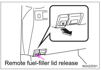
Before refueling, close all the doors, windows, and the liftgate/trunk lid, and switch the ignition OFF.
To open the fuel-filler lid, pull the remote fuel-filler lid release.

Copyright © 2026 www.toyaris4.com
