Toyota Yaris: Outer Mirror Switch / Removal
REMOVAL
PROCEDURE
1. REMOVE MULTIPLEX NETWORK MASTER SWITCH ASSEMBLY WITH FRONT ARMREST BASE UPPER PANEL
Click here
.gif)
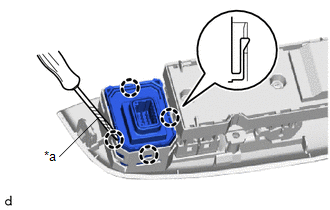
2. REMOVE OUTER MIRROR SWITCH ASSEMBLY
| (a) Using a screwdriver with its tip wrapped in protective tape, disengage the claws to remove the outer mirror switch assembly. |
|
 Components
C..
 Inspection
INSPECTION PROCEDURE 1. INSTALL OUTER MIRROR SWITCH ASSEMBLY (a) Check the mirror select and surface adjust switch. (1) Turn the mirror select and surface adjust switch to the L position...
Other information:
Toyota Yaris XP210 (2020-2026) Reapir and Service Manual: Terminals Of Ecu
TERMINALS OF ECU METER MIRROR SUB-ASSEMBLY (a) Measure the voltage and resistance according to the value(s) in the table below. Terminal No. (Symbol) Terminal Description Condition Specified Condition H61-1 (IG) - Body ground Power source for engine stop and start ECU assembly Ignition switch off Below 1 V Ignition switch ON 10...
Toyota Yaris XP210 (2020-2026) Reapir and Service Manual: Inspection
INSPECTION PROCEDURE 1. INSPECT FRONT NO. 1 SPEAKER ASSEMBLY (for RH Side) (a) Check the resistance. (1) Measure the resistance according to the value(s) in the table below. Standard Resistance: Tester Connection Condition Specified Condition K2-2 (+) - K2-1 (-) Always 4...
Categories
- Manuals Home
- Toyota Yaris Owners Manual
- Toyota Yaris Service Manual
- How to use USB mode
- G16e-gts (engine Mechanical)
- Fuel Gauge
- New on site
- Most important about car
Refueling
Before refueling, close all the doors, windows, and the liftgate/trunk lid, and switch the ignition OFF.
To open the fuel-filler lid, pull the remote fuel-filler lid release.

Copyright © 2026 www.toyaris4.com