Toyota Yaris: Outer Mirror Switch / Inspection
INSPECTION
PROCEDURE
1. INSTALL OUTER MIRROR SWITCH ASSEMBLY
(a) Check the mirror select and surface adjust switch.
| (1) Turn the mirror select and surface adjust switch to the L position. |
|
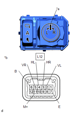
(2) Measure the resistance according to the value(s) in the table below.
Standard Resistance (for left side):
| Tester Connection | Condition | Specified Condition |
|---|---|---|
| L12-6 (B) - L12-2 (VL) | Up | Below 1 Ω |
| L12-7 (E) - L12-11 (M+) | Up | Below 1 Ω |
| L12-6 (B) - L12-2 (VL) | Off | 10 kΩ or higher |
| L12-7 (E) - L12-11 (M+) | Off | 10 kΩ or higher |
| L12-6 (B) - L12-11 (M+) | Down | Below 1 Ω |
| L12-7 (E) - L12-2 (VL) | Down | Below 1 Ω |
| L12-6 (B) - L12-11 (M+) | Off | 10 kΩ or higher |
| L12-7 (E) - L12-2 (VL) | Off | 10 kΩ or higher |
| L12-6 (B) - L12-4 (HL) | Left | Below 1 Ω |
| L12-7 (E) - L12-11 (M+) | Left | Below 1 Ω |
| L12-6 (B) - L12-4 (HL) | Off | 10 kΩ or higher |
| L12-7 (E) - L12-11 (M+) | Off | 10 kΩ or higher |
| L12-6 (B) - L12-11 (M+) | Right | Below 1 Ω |
| L12-7 (E) - L12-4 (HL) | Right | Below 1 Ω |
| L12-6 (B) - L12-11 (M+) | Off | 10 kΩ or higher |
| L12-7 (E) - L12-4 (HL) | Off | 10 kΩ or higher |
(3) Turn the mirror select and surface adjust switch to the R position.
(4) Measure the resistance according to the value(s) in the table below.
Standard Resistance (for right side):
| Tester Connection | Condition | Specified Condition |
|---|---|---|
| L12-6 (B) - L12-5 (VR) | Up | Below 1 Ω |
| L12-7 (E) - L12-11 (M+) | Up | Below 1 Ω |
| L12-6 (B) - L12-5 (VR) | Off | 10 kΩ or higher |
| L12-7 (E) - L12-11 (M+) | Off | 10 kΩ or higher |
| L12-6 (B) - L12-11 (M+) | Down | Below 1 Ω |
| L12-7 (E) - L12-5 (VR) | Down | Below 1 Ω |
| L12-6 (B) - L12-11 (M+) | Off | 10 kΩ or higher |
| L12-7 (E) - L12-5 (VR) | Off | 10 kΩ or higher |
| L12-6 (B) - L12-3 (HR) | Left | Below 1 Ω |
| L12-7 (E) - L12-11 (M+) | Left | Below 1 Ω |
| L12-6 (B) - L12-3 (HR) | Off | 10 kΩ or higher |
| L12-7 (E) - L12-11 (M+) | Off | 10 kΩ or higher |
| L12-6 (B) - L12-11 (M+) | Right | Below 1 Ω |
| L12-7 (E) - L12-3 (HR) | Right | Below 1 Ω |
| L12-6 (B) - L12-11 (M+) | Off | 10 kΩ or higher |
| L12-7 (E) - L12-3 (HR) | Off | 10 kΩ or higher |
If the result is not as specified, replace the outer mirror switch assembly.
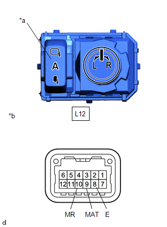
(b) Check the mirror retract switch.
| (1) Measure the resistance according to the value(s) in the table below. Standard Resistance:
If the result is not as specified, replace the outer mirror switch assembly. |
|
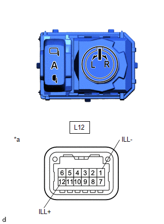
(c) Check that the LED illuminates.
| (1) Apply auxiliary battery voltage to the outer mirror switch assembly and check that the LED illuminates. OK:
If the result is not as specified, replace the outer mirror switch assembly. |
|
 Removal
REMOVAL PROCEDURE 1. REMOVE MULTIPLEX NETWORK MASTER SWITCH ASSEMBLY WITH FRONT ARMREST BASE UPPER PANEL Click here
2. REMOVE OUTER MIRROR SWITCH ASSEMBLY (a) Using a screwdriver with its tip wrapped in protective tape, disengage the claws to remove the outer mirror switch assembly...
 Installation
I..
Other information:
Toyota Yaris XP210 (2020-2026) Reapir and Service Manual: Components
COMPONENTS ILLUSTRATION *A for Intake Side *B for Exhaust Side *1 CAMSHAFT POSITION SENSOR *2 IGNITION COIL ASSEMBLY *3 ENGINE WIRE *4 O-RING Tightening torque for "Major areas involving basic vehicle performance such as moving/turning/stopping" : N*m (kgf*cm, ft...
Toyota Yaris XP210 (2020-2026) Reapir and Service Manual: Disassembly
DISASSEMBLY CAUTION / NOTICE / HINT The necessary procedures (adjustment, calibration, initialization, or registration) that must be performed after parts are removed and installed, or replaced during cylinder block removal/installation are shown below...
Categories
- Manuals Home
- Toyota Yaris Owners Manual
- Toyota Yaris Service Manual
- Brake System Control Module "A" System Voltage System Voltage Low (C137BA2)
- Key Battery Replacement
- Diagnostic Trouble Code Chart
- New on site
- Most important about car
Key Suspend Function
If a key is left in the vehicle, the functions of the key left in the vehicle are temporarily suspended to prevent theft of the vehicle.
To restore the functions, press the unlock button on the functions-suspended key in the vehicle.