Toyota Yaris: Cxpi Communication System / Power Integration No.1 System Missing Message (B235287,B235587,B235787-B235987)
DESCRIPTION
This DTC is stored when CXPI communication between the semiconductor power integration ECU, power distribution box assembly, windshield wiper relay assembly or light control LED ECU and main body ECU (multiplex network body ECU) stops for 10 seconds or more.
| LuckyWinsBet DTC No. | Detection Item | DTC Detection Condition | Trouble Area |
|---|---|---|---|
| B235287 | Power Integration No.1 System Missing Message | No communication between semiconductor power integration ECU and main body ECU (multiplex network body ECU) for 10 seconds or more |
|
| B235587 | Power Distribution Box Missing Message | No communication between power distribution box assembly and main body ECU (multiplex network body ECU) for 10 seconds or more |
|
| B235787 | Wiper Module Missing Message | No communication between windshield wiper relay assembly and main body ECU (multiplex network body ECU) for 10 seconds or more |
|
| B235887 | Smart LDM Left Missing Message | No communication between light control LED ECU LH and main body ECU (multiplex network body ECU) for 10 seconds or more |
|
| B235987 | Smart LDM Right Missing Message | No communication between light control LED ECU RH and main body ECU (multiplex network body ECU) for 10 seconds or more |
|
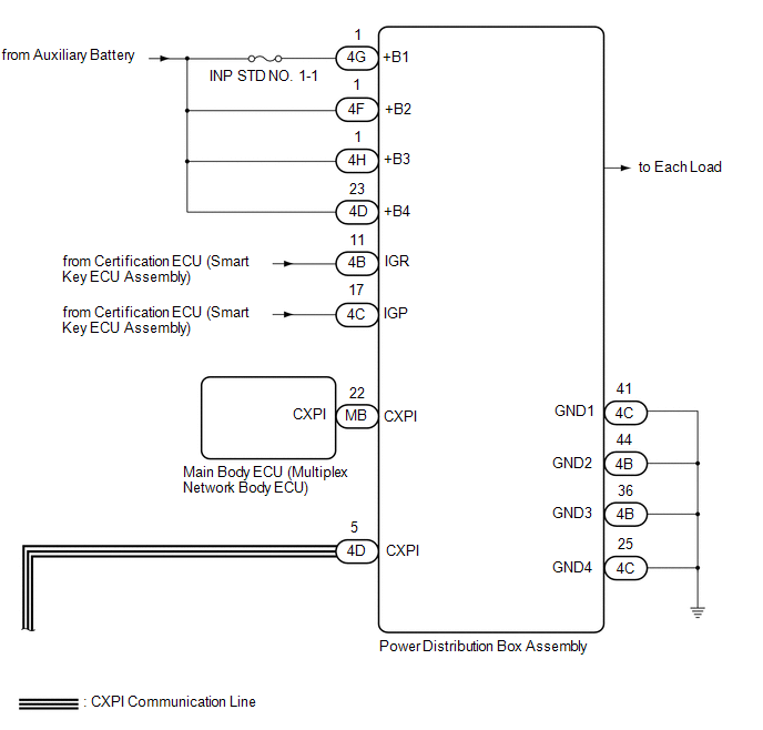
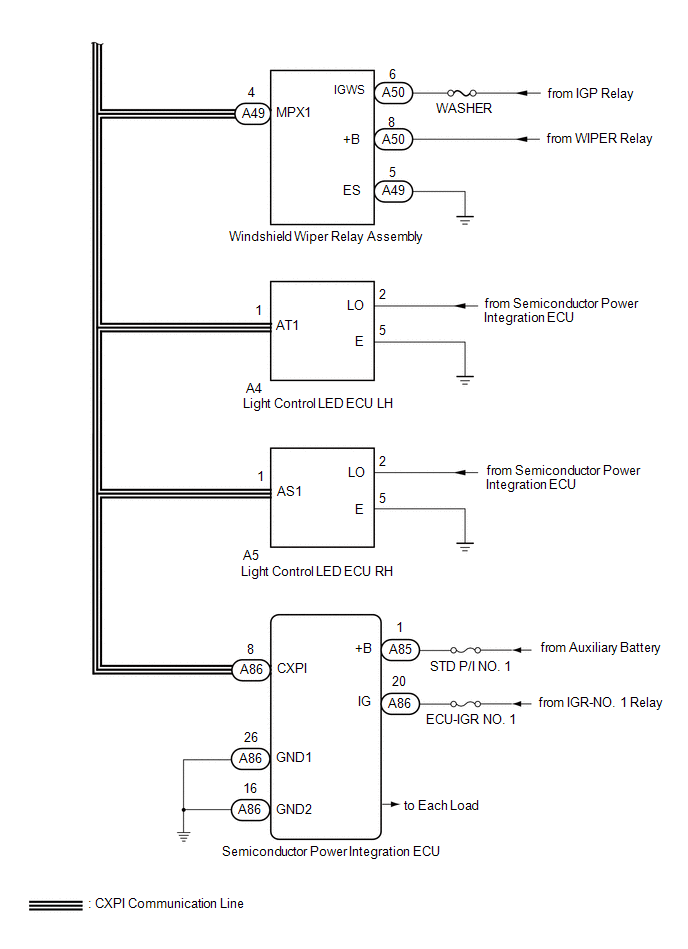
WIRING DIAGRAM
CAUTION / NOTICE / HINT
NOTICE:
- Inspect the fuses for circuits related to this system before performing the following procedure.
- Recognition code registration is necessary when replacing the main body ECU (multiplex network body ECU).
- If the main body ECU (multiplex network body ECU) is replaced, refer to the Registration.
-
When disconnecting and reconnecting the auxiliary battery, there is an automatic learning function that completes learning when the respective system is used.
Click here

-
Some parts must be initialized and set when replacing or removing and installing parts.
Click here

PROCEDURE
| 1. | CLEAR DTC |
(a) Clear the DTCs.
Body Electrical > Main Body > Clear DTCs
|

| 2. | CHECK FOR DTC |
(a) Check for DTCs.
Body Electrical > Main Body > Trouble Codes| Result | Proceed to |
|---|---|
| B235287, B235587, B235787, B235887 and B235987 are output | A |
| B235287, B235787, B235887 and B235987 are output | B |
| Only B235587 is output | C |
| Only B235287 is output | D |
| Only B235787 is output | E |
| Only B235887 is output | F |
| Only B235987 is output | G |
| DTCs are not output | H |
| B |
 | GO TO STEP 4 |
| C |
 | GO TO STEP 6 |
| D |
 | GO TO STEP 7 |
| E |
 | GO TO STEP 9 |
| F |
 | GO TO STEP 11 |
| G |
 | GO TO STEP 13 |
| H |
 | USE SIMULATION METHOD TO CHECK |
|

| 3. | CHECK POWER DISTRIBUTION BOX ASSEMBLY |
(a) Remove the power distribution box assembly.
Click here

(b) Remove the main body ECU (multiplex network body ECU) from the power distribution box assembly.
(c) Disconnect the 4D power distribution box assembly connector.
(d) Measure the resistance according to the value(s) in the table below.
Standard Resistance| Tester Connection | Condition | Specified Condition |
|---|---|---|
| MB-22 (CXPI) - 4D-5 | Always | Below 1 Ω |
| OK |
 | REPLACE MAIN BODY ECU (MULTIPLEX NETWORK BODY ECU) |
| NG |
 | REPLACE POWER DISTRIBUTION BOX ASSEMBLY |
| 4. | CHECK POWER DISTRIBUTION BOX ASSEMBLY |
(a) Remove the power distribution box assembly.
Click here

(b) Remove the main body ECU (multiplex network body ECU) from the power distribution box assembly.
(c) Disconnect the 4D power distribution box assembly connector.
(d) Measure the resistance according to the value(s) in the table below.
Standard Resistance:
| Tester Connection | Condition | Specified Condition |
|---|---|---|
| MB-22 (CXPI) - 4D-5 | Always | Below 1 Ω |
| NG |
 | REPLACE POWER DISTRIBUTION BOX ASSEMBLY |
|

| 5. | CHECK HARNESS AND CONNECTOR (POWER DISTRIBUTION BOX ASSEMBLY - SEMICONDUCTOR POWER INTEGRATION ECU) |
(a) Disconnect the cable from the negative (-) auxiliary battery terminal.
(b) Disconnect the 4D power distribution box assembly connector.
(c) Disconnect the A49 windshield wiper relay assembly connector.
(d) Disconnect the A4 light control LED ECU LH connector.
(e) Disconnect the A5 light control LED ECU RH connector.
(f) Disconnect the A86 semiconductor power integration ECU connector.
(g) Measure the voltage according to the value(s) in the table below.
Standard Resistance:
| Tester Connection | Condition | Specified Condition |
|---|---|---|
| 4D-5 - A86-8 (CXPI) | Cable disconnected from negative (-) auxiliary battery terminal | Below 1 Ω |
| 4D-5 - Body ground | Cable disconnected from negative (-) auxiliary battery terminal | 10 kΩ or higher |
| OK |
 | REPLACE MAIN BODY ECU (MULTIPLEX NETWORK BODY ECU) |
| NG |
 | REPAIR OR REPLACE HARNESS OR CONNECTOR |
| 6. | CHECK HARNESS AND CONNECTOR (SEMICONDUCTOR POWER INTEGRATION ECU - BATTERY AND BODY GROUND) |
(a) Turn the ignition switch off.
(b) Disconnect the cable from the negative (-) auxiliary battery terminal.
(c) Disconnect the 4B and 4C power distribution box assembly connectors.
(d) Measure the resistance according to the value(s) in the table below.
Standard Resistance:
| Tester Connection | Condition | Specified Condition |
|---|---|---|
| 4C-41 (GND1) - Body ground | Always | Below 1 Ω |
| 4B-44 (GND2) - Body ground | Always | Below 1 Ω |
| 4B-36 (GND3) - Body ground | Always | Below 1 Ω |
| 4C-25 (GND4) - Body ground | Always | Below 1 Ω |
(e) Connect the cable to the negative (-) auxiliary battery terminal.
(f) Measure the voltage according to the value(s) in the table below.
Standard Voltage:
| Tester Connection | Switch Condition | Specified Condition |
|---|---|---|
| 4G-1 (+B1) - Body ground | Ignition switch off | 11 to 14 V |
| 4F-1 (+B2) - Body ground | Ignition switch off | 11 to 14 V |
| 4H-1 (+B3) - Body ground | Ignition switch off | 11 to 14 V |
| 4D-23 (+B4) - Body ground | Ignition switch off | 11 to 14 V |
| 4B-11 (IGR) - Body ground | Ignition switch ON | 11 to 14 V |
| 4C-17 (IGP) - Body ground | Ignition switch ON | 11 to 14 V |
| OK |
 | REPLACE POWER DISTRIBUTION BOX ASSEMBLY |
| NG |
 | REPAIR OR REPLACE HARNESS OR CONNECTOR |
| 7. | CHECK HARNESS AND CONNECTOR (SEMICONDUCTOR POWER INTEGRATION ECU - BATTERY AND BODY GROUND) |
(a) Turn the ignition switch off.
(b) Disconnect the cable from the negative (-) auxiliary battery terminal.
(c) Disconnect the A85 and A86 semiconductor power integration ECU connectors.
(d) Measure the resistance according to the value(s) in the table below.
Standard Resistance:
| Tester Connection | Condition | Specified Condition |
|---|---|---|
| A86-26 (GND1) - Body ground | Always | Below 1 Ω |
(e) Connect the cable to the negative (-) auxiliary battery terminal.
(f) Measure the voltage according to the value(s) in the table below.
Standard Voltage:
| Tester Connection | Switch Condition | Specified Condition |
|---|---|---|
| A85-1 (+B) - Body ground | Ignition switch ON | 8 to 14 V |
| A86-20 (IG) - Body ground | Ignition switch ON | 8 to 14 V |
| NG |
 | REPAIR OR REPLACE HARNESS OR CONNECTOR |
|

| 8. | CHECK HARNESS AND CONNECTOR (SEMICONDUCTOR POWER INTEGRATION ECU - POWER DISTRIBUTION BOX ASSEMBLY) |
(a) Turn the ignition switch off.
(b) Disconnect the cable from the negative (-) auxiliary battery terminal.
(c) Disconnect the 4D power distribution box assembly connector.
(d) Disconnect the A86 semiconductor power integration ECU connector.
(e) Measure the resistance according to the value(s) in the table below.
Standard Resistance:
| Tester Connection | Condition | Specified Condition |
|---|---|---|
| A86-8 (CXPI) - 4D-5 | Cable disconnected from negative (-) auxiliary battery terminal | Below 1 Ω |
| A86-8 (CXPI) - Body ground | Cable disconnected from negative (-) auxiliary battery terminal | 10 kΩ or higher |
| OK |
 | REPLACE SEMICONDUCTOR POWER INTEGRATION ECU |
| NG |
 | REPAIR OR REPLACE HARNESS OR CONNECTOR |
| 9. | CHECK HARNESS AND CONNECTOR (WINDSHIELD WIPER RELAY ASSEMBLY - BATTERY AND BODY GROUND) |
(a) Disconnect the A49 and A50 windshield wiper relay assembly connectors.
(b) Measure the resistance and voltage according to the value(s) in the table below.
Standard Resistance:
| Tester Connection | Condition | Specified Condition |
|---|---|---|
| A49-5 (ES) - Body ground | Always | Below 1 Ω |
Standard Voltage:
| Tester Connection | Switch Condition | Specified Condition |
|---|---|---|
| A50-6 (IGWS) - Body ground | Ignition switch ON | 11 to 14 V |
| A50-8 (+B) - Body ground | Ignition switch ON or less than approximately 60 seconds after ignition switch turned off | 11 to 14 V |
| A50-8 (+B) - Body ground | Approximately 60 seconds or more after ignition switch turned off | Below 1 V |
| NG |
 | REPAIR OR REPLACE HARNESS OR CONNECTOR |
|

| 10. | CHECK HARNESS AND CONNECTOR (WINDSHIELD WIPER RELAY ASSEMBLY - POWER DISTRIBUTION BOX ASSEMBLY) |
(a) Turn the ignition switch off.
(b) Disconnect the cable from the negative (-) auxiliary battery terminal.
(c) Disconnect the A49 windshield wiper relay assembly connector.
(d) Disconnect the 4D power distribution box assembly connector.
(e) Measure the resistance according to the value(s) in the table below.
Standard Resistance:
| Tester Connection | Condition | Specified Condition |
|---|---|---|
| A49-4 (MPX1) - 4D-5 | Cable disconnected from negative (-) auxiliary battery terminal | Below 1 Ω |
| A49-4 (MPX1) - Body ground | Cable disconnected from negative (-) auxiliary battery terminal | 10 kΩ or higher |
| OK |
 | REPLACE WINDSHIELD WIPER RELAY ASSEMBLY |
| NG |
 | REPAIR OR REPLACE HARNESS OR CONNECTOR |
| 11. | CHECK HARNESS AND CONNECTOR (LIGHT CONTROL LED ECU LH - BATTERY AND BODY GROUND) |
(a) Disconnect the A4 light control LED ECU LH connector.
(b) Measure the resistance and voltage according to the value(s) in the table below.
Standard Resistance:
| Tester Connection | Condition | Specified Condition |
|---|---|---|
| A4-5 (E) - Body ground | Always | Below 1 Ω |
Standard Voltage:
| Tester Connection | Condition | Specified Condition |
|---|---|---|
| A4-2 (LO) - Body ground | Taillight on | 9.5 to 14 V |
| A4-2 (LO) - Body ground | Taillight off | Below 1 V |
| NG |
 | REPAIR OR REPLACE HARNESS OR CONNECTOR |
|

| 12. | CHECK HARNESS AND CONNECTOR (LIGHT CONTROL LED ECU LH - POWER DISTRIBUTION BOX ASSEMBLY) |
(a) Turn the ignition switch off.
(b) Disconnect the cable from the negative (-) auxiliary battery terminal.
(c) Disconnect the A4 light control LED ECU LH connector.
(d) Disconnect the 4D power distribution box assembly connector.
(e) Measure the resistance according to the value(s) in the table below.
Standard Resistance:
| Tester Connection | Condition | Specified Condition |
|---|---|---|
| A4-1 (AT1) - 4D-5 | Cable disconnected from negative (-) auxiliary battery terminal | Below 1 Ω |
| A4-1 (AT1) - Body ground | Cable disconnected from negative (-) auxiliary battery terminal | 10 kΩ or higher |
| OK |
 | REPLACE LIGHT CONTROL LED ECU LH |
| NG |
 | REPAIR OR REPLACE HARNESS OR CONNECTOR |
| 13. | CHECK HARNESS AND CONNECTOR (LIGHT CONTROL LED ECU RH - BATTERY AND BODY GROUND) |
(a) Disconnect the A5 light control LED ECU RH connector.
(b) Measure the resistance and voltage according to the value(s) in the table below.
Standard Resistance:
| Tester Connection | Condition | Specified Condition |
|---|---|---|
| A5-5 (E) - Body ground | Always | Below 1 Ω |
Standard Voltage:
| Tester Connection | Condition | Specified Condition |
|---|---|---|
| A5-2 (LO) - Body ground | Taillight on | 9.5 to 14 V |
| A5-2 (LO) - Body ground | Taillight off | Below 1 V |
| NG |
 | REPAIR OR REPLACE HARNESS OR CONNECTOR |
|

| 14. | CHECK HARNESS AND CONNECTOR (LIGHT CONTROL LED ECU RH - POWER DISTRIBUTION BOX ASSEMBLY) |
(a) Turn the ignition switch off.
(b) Disconnect the cable from the negative (-) auxiliary battery terminal.
(c) Disconnect the A5 light control LED ECU RH connector.
(d) Disconnect the 4D power distribution box assembly connector.
(e) Measure the resistance according to the value(s) in the table below.
Standard Resistance:
| Tester Connection | Condition | Specified Condition |
|---|---|---|
| A5-1 (AS1) - 4D-5 | Cable disconnected from negative (-) auxiliary battery terminal | Below 1 Ω |
| A5-1 (AS1) - Body ground | Cable disconnected from negative (-) auxiliary battery terminal | 10 kΩ or higher |
| OK |
 | REPLACE LIGHT CONTROL LED ECU RH |
| NG |
 | REPAIR OR REPLACE HARNESS OR CONNECTOR |


Other information:
Toyota Yaris XP210 (2020-2026) Reapir and Service Manual: Vehicle Control History
VEHICLE CONTROL HISTORY DESCRIPTION Vehicle Control History is a function that captures and stores ECU data when triggered by specific vehicle behavior. It may be possible to determine the cause of the malfunction by checking the vehicle history information and freeze frame data...
Toyota Yaris XP210 (2020-2026) Reapir and Service Manual: Installation
INSTALLATION CAUTION / NOTICE / HINT NOTICE: This procedure includes the installation of small-head bolts. Refer to Small-Head Bolts of Basic Repair Hint to identify the small-head bolts. Click here PROCEDURE 1. INSTALL FUEL PRESSURE SENSOR HINT: Perform "Inspection After Repair" after replacing the fuel pressure sensor...
Categories
- Manuals Home
- Toyota Yaris Owners Manual
- Toyota Yaris Service Manual
- G16e-gts (engine Mechanical)
- How to use USB mode
- Engine & Hybrid System
- New on site
- Most important about car
Supplemental Restraint System (SRS) Precautions
The front and side supplemental restraint systems (SRS) include different types of air bags. Please verify the different types of air bags which are equipped on your vehicle by locating the “SRS AIRBAG” location indicators. These indicators are visible in the area where the air bags are installed.
The air bags are installed in the following locations:
The steering wheel hub (driver air bag) The front passenger dashboard (front passenger air bag) The outboard sides of the front seatbacks (side air bags) The front and rear window pillars, and the roof edge along both sides (curtain air bags)