Toyota Yaris: Fuel Pressure Sensor (for High Pressure) / Installation
INSTALLATION
CAUTION / NOTICE / HINT
NOTICE:
This procedure includes the installation of small-head bolts. Refer to Small-Head Bolts of Basic Repair Hint to identify the small-head bolts.
Click here

PROCEDURE
1. INSTALL FUEL PRESSURE SENSOR
HINT:
Perform "Inspection After Repair" after replacing the fuel pressure sensor.
Click here

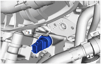
| (a) Temporarily install the fuel pressure sensor to the fuel delivery pipe as shown in the illustration. NOTICE: Make sure that the cutout of the fuel pressure sensor are facing upward. |
|
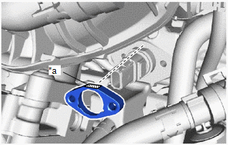
| (b) Temporarily install the No. 1 fuel pressure sensor holder to the fuel delivery pipe as shown in the illustration. NOTICE: Make sure that the cutout of the fuel pressure sensor holder are facing upward. |
|
(c) Using an 8 mm socket wrench, install the 2 bolts.
Torque:
10 N·m {102 kgf·cm, 7 ft·lbf}
(d) Connect the fuel pressure sensor connector.
2. INSTALL NO. 1 ENGINE COVER SUB-ASSEMBLY
Click here

3. CONNECT CABLE TO NEGATIVE AUXILIARY BATTERY TERMINAL
Click here

4. INITIALIZATION AFTER RECONNECTING AUXILIARY BATTERY TERMINAL
HINT:
When disconnecting and reconnecting the auxiliary battery, there is an automatic learning function that completes learning when the respective system is used.
Click here

5. INSPECT FOR FUEL LEAK
Click here

6. PERFORM INITIALIZATION
(a) Perform "Inspection After Repair" after replacing the fuel pressure sensor.
Click here

 Inspection
INSPECTION PROCEDURE 1. INSPECT FUEL PRESSURE SENSOR (a) Check the fuel pressure sensor output voltage. (1) Apply 5 V between terminals 1 (VC) and 2 (E2)...
 Fuel Pump
..
Other information:
Toyota Yaris XP210 (2020-2026) Owner's Manual: Fuel Consumption Display
Information regarding the fuel economy is displayed. Displays the fuel economy for the past 60 minutes. Displays the fuel economy every minute for the past 1 to 10 minutes. Displays the fuel economy every 10 minutes for the past 10 to 60 minutes...
Toyota Yaris XP210 (2020-2026) Reapir and Service Manual: Front Door Courtesy Switch Circuit
DESCRIPTION The main body ECU (multiplex network body ECU) detects the condition of the front door courtesy light switch assembly. WIRING DIAGRAM CAUTION / NOTICE / HINT NOTICE: Before replacing the main body ECU (multiplex network body ECU), refer to Registration...
Categories
- Manuals Home
- Toyota Yaris Owners Manual
- Toyota Yaris Service Manual
- Fuel Gauge
- Opening and Closing the Liftgate/Trunk Lid
- Engine Start Function When Key Battery is Dead
- New on site
- Most important about car
Supplemental Restraint System (SRS) Precautions
The front and side supplemental restraint systems (SRS) include different types of air bags. Please verify the different types of air bags which are equipped on your vehicle by locating the “SRS AIRBAG” location indicators. These indicators are visible in the area where the air bags are installed.
The air bags are installed in the following locations:
The steering wheel hub (driver air bag) The front passenger dashboard (front passenger air bag) The outboard sides of the front seatbacks (side air bags) The front and rear window pillars, and the roof edge along both sides (curtain air bags)