Toyota Yaris: Fuel Pressure Sensor (for High Pressure) / Inspection
INSPECTION
PROCEDURE
1. INSPECT FUEL PRESSURE SENSOR
(a) Check the fuel pressure sensor output voltage.
| (1) Apply 5 V between terminals 1 (VC) and 2 (E2). NOTICE:
HINT: If a stable power supply is not available, connect 4 nickel-metal hydride batteries (1.2 V each) or equivalent in series. |
|
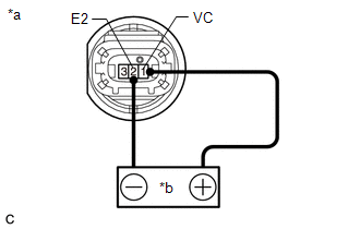
| (2) Measure the voltage according to the value(s) in the table below. Standard Voltage:
*: The output voltage changes depending on the voltage applied to the terminals. If the result is not as specified, replace the fuel pressure sensor. |
|
 Removal
REMOVAL CAUTION / NOTICE / HINT The necessary procedures (adjustment, calibration, initialization or registration) that must be performed after parts are removed and installed, or replaced during fuel pressure sensor removal/installation are shown below...
 Installation
INSTALLATION CAUTION / NOTICE / HINT NOTICE: This procedure includes the installation of small-head bolts. Refer to Small-Head Bolts of Basic Repair Hint to identify the small-head bolts...
Other information:
Toyota Yaris XP210 (2020-2026) Owner's Manual: Replacing Exterior Light Bulbs
Headlights/Daytime running lights (With halogen headlights) Make sure the ignition is switched off, and the headlight switch is off. Lift the hood. Disconnect the connector from the bulb. Detach the sealing cover from the bulb. Retaining spring Sealing cover Unhook the bulb retaining spring...
Toyota Yaris XP210 (2020-2026) Reapir and Service Manual: Engine Difficult to Start
DESCRIPTION Problem Symptom Suspected Area Trouble Area Engine does not crank Engine cranks slowly Auxiliary battery depletion Starter malfunction Starter system Auxiliary battery depletion Starter malfunction Starter circuit Excessive engine friction Engine Engine assembly Starting time is long Engine speed fluctuation due to abnormal combustion Idle speed too low or high The engine stalls immediately after starting Strong engine vibration due to above symptoms Ignition malfunction Deviation in air fuel ratio (Excessive or insufficient intake air volume or fuel supply) Insufficient compression Changes in load from another system Ignition system Spark plug Ignition coil assembly Fuel system Direct fuel injector assembly Port fuel injector assembly Fuel pump assembly (for high pressure side) Fuel pump (for low pressure side) Fuel pump control circuit Fuel suction plate sub-assembly Fuel main valve assembly Fuel line Purge VSV system Fuel quality (existence of foreign matter, degradation) Intake and exhaust systems Mass air flow meter sub-assembly Intake system (Air leaks or deposit accumulation) Throttle body with motor assembly Air fuel ratio sensor (sensor 1) Air fuel ratio sensor (sensor 2) Cam timing oil control solenoid assembly Variable Valve Timing system (VVT system) Other control systems ECM Wire harness or connector Knock control sensor Engine coolant temperature sensor Immobiliser system Engine Water control valve Engine assembly Crankshaft position sensor High load from another system Air conditioning system Power steering system Electrical load signal system SYMPTOM AND CAUSE OF SYSTEM MALFUNCTION HINT: The following are descriptions of the characteristics of each system malfunction...
Categories
- Manuals Home
- Toyota Yaris Owners Manual
- Toyota Yaris Service Manual
- Removal
- Maintenance
- Engine & Hybrid System
- New on site
- Most important about car
Break-In Period
No special break-in is necessary, but a few precautions in the first 600 miles (1,000 km) may add to the performance, economy, and life of the vehicle.
Do not race the engine. Do not maintain one constant speed, either slow or fast, for a long period of time. Do not drive constantly at full-throttle or high engine rpm for extended periods of time. Avoid unnecessary hard stops. Avoid full-throttle starts.