Toyota Yaris: Charging System / Battery Monitor Module General Electrical Failure (P058A01)
DESCRIPTION
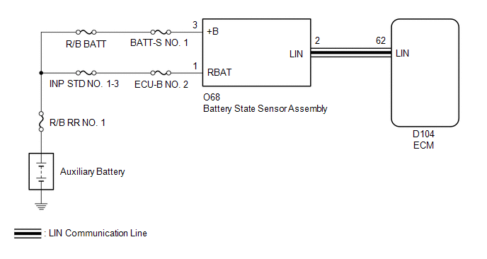
The battery state sensor assembly detects the voltage, current and temperature of the auxiliary battery. The charging condition is calculated from the voltage and current and output to the ECM. The ECM sends an instruction to generate voltage to the generator assembly based on that signal. Also, the auxiliary battery temperature is calculated from the change in the resistance value of the thermistor built into the battery state sensor assembly and output to the ECM. The ECM reduces the charging current when the auxiliary battery is hot and protects the auxiliary battery based on this signal.
| DTC No. | Detection Item | DTC Detection Condition | Trouble Area | MIL | Note |
|---|---|---|---|---|---|
| P058A01 | Battery Monitor Module General Electrical Failure | Any of the following conditions is met with the ignition switch ON. (1 trip detection logic):
|
| Does not come on | SAE Code: P058A |
WIRING DIAGRAM
CAUTION / NOTICE / HINT
NOTICE:
- Inspect the fuses for circuits related to this system before performing the following inspection procedure.
-
When P162B87 (Lost Communication with Battery Monitor Module Missing Message) is output at the same time, perform the inspection for P162B87 (Lost Communication with Battery Monitor Module Missing Message) first.
Click here

PROCEDURE
| 1. | CHECK BATTERY STATE SENSOR ASSEMBLY INSTALLATION |
HINT:
Click here

| NG |
 | INSTALL BATTERY STATE SENSOR ASSEMBLY CORRECTLY |
|

| 2. | CHECK CHARGING SYSTEM |
HINT:
Click here

| NG |
 | REPAIR OR REPLACE CHARGING SYSTEM |
|

| 3. | CHECK HARNESS AND CONNECTOR (POWER SOURCE CIRCUIT) |
| (a) Disconnect the battery state sensor assembly connector. |
|
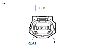
(b) Measure the voltage according to the value(s) in the table below.
Standard Voltage:
| Tester Connection | Condition | Specified Condition |
|---|---|---|
| O68-3 (+B) - Body ground | Always | 11 to 14 V |
| O68-1 (RBAT) - Body ground | Always | 11 to 14 V |
| OK |
 | REPLACE BATTERY STATE SENSOR ASSEMBLY |
| NG |
 | REPAIR OR REPLACE HARNESS OR CONNECTOR |
 Vehicle Control History
VEHICLE CONTROL HISTORY CHECK VEHICLE CONTROL HISTORY (a) Connect the GTS to the DLC3. (b) Turn the ignition switch to ON. (c) Turn the GTS on. (d) Enter the following menus: Powertrain / Engine / Utility / Vehicle Control History (RoB)...
 Generator Control Circuit Internal Electronic Failure (P062049)
DESCRIPTION The alternator performs self-diagnosis of its internal circuits to detect malfunctions (open or short circuits). The ECM receives the result via LIN communication and stores a DTC...
Other information:
Toyota Yaris XP210 (2020-2026) Reapir and Service Manual: Removal
REMOVAL CAUTION / NOTICE / HINT The necessary procedures (adjustment, calibration, initialization or registration) that must be performed after parts are removed and installed, or replaced during fuel pressure sensor removal/installation are shown below...
Toyota Yaris XP210 (2020-2026) Reapir and Service Manual: Glossary Of Sae And Toyota Terms
GLOSSARY OF SAE AND TOYOTA TERMS This glossary lists all SAE-J1930 terms and abbreviations used in this manual in compliance with SAE recommendations, as well as their TOYOTA equivalents. SAE Abbreviation SAE Term TOYOTA Term ( )-Abbreviation A/C Air Conditioning Air Conditioner ACL Air Cleaner Air Cleaner, A/CL AIR Secondary Air Injection Air Injection (AI) AP Accelerator Pedal - B+ Battery Positive Voltage +B, Battery Voltage BARO Barometric Pressure HAC CAC Charge Air Cooler Intercooler CARB Carburetor Carburetor CFI Continuous Fuel Injection - CKP Crankshaft Position Crank Angle CL Closed Loop Closed Loop CMP Camshaft Position Cam Angle CPP Clutch Pedal Position - CTOX Continuous Trap Oxidizer - CTP Closed Throttle Position LL ON, Idle ON DFI Direct Fuel Injection Direct Injection (DI...
Categories
- Manuals Home
- Toyota Yaris Owners Manual
- Toyota Yaris Service Manual
- Battery Monitor Module General Electrical Failure (P058A01)
- Power Integration No.1 System Missing Message (B235287,B235587,B235787-B235987)
- How to use USB mode
- New on site
- Most important about car
Front Seat Belt Pretensioners
The front seat belt pretensioners are designed to deploy in moderate or severe frontal, near frontal collisions.
In addition, the pretensioners operate when a side collision or a rollover accident is detected. The pretensioners operate differently depending on what types of air bags are equipped. For more details about the seat belt pretensioner operation, refer to the SRS Air Bag Deployment Criteria.