Toyota Yaris: Fuel Pressure Sensor (for High Pressure) / Removal
REMOVAL
CAUTION / NOTICE / HINT
The necessary procedures (adjustment, calibration, initialization or registration) that must be performed after parts are removed and installed, or replaced during fuel pressure sensor removal/installation are shown below.
Necessary Procedures After Parts Removed/Installed/Replaced| Replaced Part or Performed Procedure | Necessary Procedure | Effect/Inoperative Function when Necessary Procedure not Performed | Link |
|---|---|---|---|
| Replacement of fuel pressure sensor (for high pressure side) | Inspection after repair |
|
|

CAUTION:
-
Never perform work on fuel system components near any possible ignition sources.
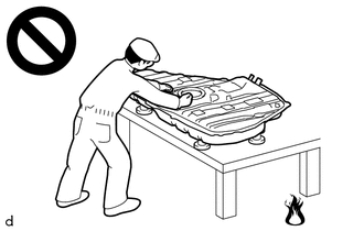
- Vaporized fuel could ignite, resulting in a serious accident.
-
Do not perform work on fuel system components without first disconnecting the cable from the negative (-) auxiliary battery terminal.
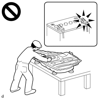
- Sparks could cause vaporized fuel to ignite, resulting in a serious accident.
NOTICE:
- After the ignition switch is turned off, the radio and display receiver assembly records various types of memory and settings. As a result, after turning the ignition switch off, make sure to wait at least 120 seconds before disconnecting the cable from the negative (-) auxiliary battery terminal.
-
This procedure includes the removal of small-head bolts. Refer to Small-Head Bolts of Basic Repair Hint to identify the small-head bolts.
Click here

HINT:
When the cable is disconnected/reconnected to the auxiliary battery terminal, systems temporarily stop operating. However, each system has a function that completes learning the first time the system is used.
-
Learning completes when vehicle is driven
Effect/Inoperative Function When Necessary Procedures are not Performed
Necessary Procedures
Link
Lane tracing assist system
Drive the vehicle straight ahead at 35 km/h (22 mph) or more for 5 second or more.

Pre-collision system
Stop and start system
Drive the vehicle until stop and start control is permitted (approximately 5 to 60 minutes)

-
Learning completes when vehicle is operated normally
Effect/Inoperative Function When Necessary Procedures are not Performed
Necessary Procedures
Link
Power door lock control system
- Back door opener
Perform door unlock operation with door control switch or electrical key transmitter sub-assembly switch.

Air conditioning system
After the ignition switch is turned to ON, the servo motor standard position is recognized.
-
PROCEDURE
1. DISCHARGE FUEL SYSTEM PRESSURE
Click here

2. PRECAUTION
NOTICE:
After turning the ignition switch off, waiting time may be required before disconnecting the cable from the negative (-) auxiliary battery terminal.
Click here

3. DISCONNECT CABLE FROM NEGATIVE AUXILIARY BATTERY TERMINAL
Click here

4. REMOVE NO. 1 ENGINE COVER SUB-ASSEMBLY
Click here

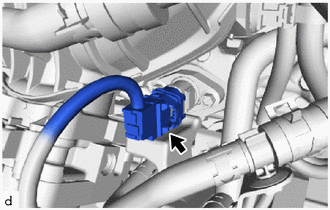
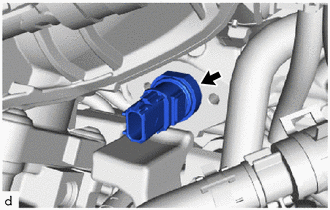
5. REMOVE FUEL PRESSURE SENSOR
| (a) Disconnect the fuel pressure sensor connector. |
|
| (b) Using an 8 mm socket wrench, remove the 2 bolts and No. 1 fuel pressure sensor holder. |
|
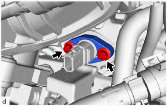
| (c) Remove the fuel pressure sensor from the fuel delivery pipe. NOTICE:
|
|
 Components
COMPONENTS ILLUSTRATION
*1 FUEL PRESSURE SENSOR *2 NO. 1 FUEL PRESSURE SENSOR HOLDER *3 NO. 1 ENGINE COVER SUB-ASSEMBLY - -
Tightening torque for "Major areas involving basic vehicle performance such as moving/turning/stopping": N*m (kgf*cm, ft...
 Inspection
INSPECTION PROCEDURE 1. INSPECT FUEL PRESSURE SENSOR (a) Check the fuel pressure sensor output voltage. (1) Apply 5 V between terminals 1 (VC) and 2 (E2)...
Other information:
Toyota Yaris XP210 (2020-2026) Reapir and Service Manual: On-vehicle Inspection
ON-VEHICLE INSPECTION PROCEDURE 1. REMOVE NO. 1 ENGINE UNDER COVER ASSEMBLY Click here 2. DRAIN ENGINE OIL Click here 3. DRAIN ENGINE COOLANT Click here 4. REMOVE FAN AND GENERATOR V BELT Click here 5. REMOVE OIL FILTER BRACKET SUB-ASSEMBLY (a) Slide the clip and separate the No...
Toyota Yaris XP210 (2020-2026) Owner's Manual: Rear View Parking Camera Location
4-Door 5-Door Switching to the Rear View Monitor Display Shift the shift lever to R with the ignition switched ON to switch the display to the rear view monitor display. When the shift lever is shifted from R to another shift lever position, the screen returns to the previous display...
Categories
- Manuals Home
- Toyota Yaris Owners Manual
- Toyota Yaris Service Manual
- Auto Lock/Unlock Function
- Maintenance
- Fuel Gauge
- New on site
- Most important about car
Fuel Gauge
The fuel gauge shows approximately how much fuel is remaining in the tank when the ignition is switched ON. We recommend keeping the tank over 1/4 full.
