Toyota Yaris: Wiper And Washer System / Wiper Module Missing Message (B235787)
DESCRIPTION
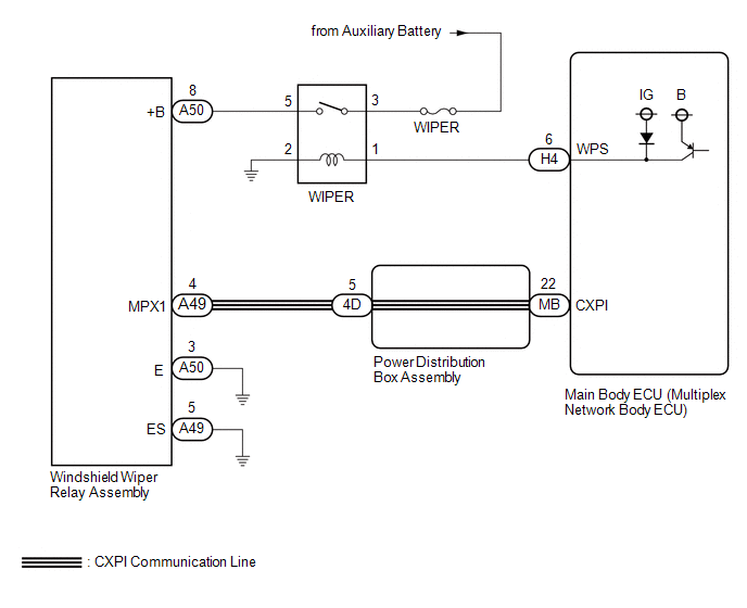
The main body ECU (multiplex network body ECU) and windshield wiper relay assembly communicate via CXPI communication. The main body ECU (multiplex network body ECU) stores this DTC if communication becomes abnormal.
| DTC No. | Detection Item | DTC Detection Condition | Trouble Area | Memory | DTC Output from |
|---|---|---|---|---|---|
| B235787 | Wiper Module Missing Message |
|
| ○ | Main Body |
WIRING DIAGRAM
CAUTION / NOTICE / HINT
NOTICE:
- Inspect the fuses of circuits related to this system before performing the following procedure.
-
If the main body ECU (multiplex network body ECU) is replaced, refer to the Registration.
Click here
.gif)
HINT:
The wiper and washer system uses the CXPI communication system. First, confirm that there is no malfunction in the CXPI communication system.
PROCEDURE
| 1. | CHECK HARNESS AND CONNECTOR (WINDSHIELD WIPER RELAY ASSEMBLY - POWER DISTRIBUTION BOX ASSEMBLY) |
(a) Disconnect the A49 windshield wiper relay assembly connector.
(b) Disconnect the 4D power distribution box assembly.
(c) Measure the resistance according to the value(s) in the table below.
Standard Resistance:
| Tester Connection | Condition | Specified Condition |
|---|---|---|
| A49-4 (MPX1) - 4D-5 | Always | Below 1 Ω |
| A49-4 (MPX1) or 4D-5 - Body ground | Always | 10 kΩ or higher |
| NG |
.gif) | REPAIR OR REPLACE HARNESS OR CONNECTOR |
|
.gif)
| 2. | CHECK HARNESS AND CONNECTOR (POWER DISTRIBUTION BOX ASSEMBLY - MAIN BODY ECU (MULTIPLEX NETWORK BODY ECU)) |
(a) Disconnect the 4D power distribution box assembly connector.
(b) Disconnect the MB main body ECU (multiplex network body ECU) connector.
(c) Measure the resistance according to the value(s) in the table below.
Standard Resistance:
| Tester Connection | Condition | Specified Condition |
|---|---|---|
| 4D-5 - MB-22 (CXPI) | Always | Below 1 Ω |
| 4D-5 or MB-22 (CXPI) - Body ground | Always | 10 kΩ or higher |
| NG |
| REPLACE POWER DISTRIBUTION BOX ASSEMBLY |
|
| 3. | CHECK MAIN BODY ECU (MULTIPLEX NETWORK BODY ECU) |
(a) Connect the 4D power distribution box assembly connector.
(b) Check for voltage and pulses according to the value(s) in the table below.
Standard Voltage:
| Tester Connection | Switch Condition | Specified Condition |
|---|---|---|
| A49-4 (MPX1) - Body ground | Ignition switch ON | Pulse generation |
| A49-4 (MPX1) - Body ground | Ignition switch off | 11 to 14 V |
| NG |
| REPLACE MAIN BODY ECU (MULTIPLEX NETWORK BODY ECU) |
|
| 4. | PERFORM ACTIVE TEST USING GTS (WIPER POWER RELAY) |
(a) Perform the Active Test according to the display on the GTS.
Body Electrical > Main Body > Active Test| Tester Display | Measurement Item | Control Range | Diagnostic Note |
|---|---|---|---|
| Wiper Power Relay | Function to operate the IG1 wiper relay | OFF or ON | - |
| Tester Display |
|---|
| Wiper Power Relay |
OK:
IG1 Wiper relay operates normally.
| NG |
| GO TO STEP 10 |
|
| 5. | CHECK HARNESS AND CONNECTOR (WINDSHIELD WIPER RELAY ASSEMBLY - BODY GROUND) |

| *a | Front view of wire harness connector (to Windshield Wiper Relay Assembly) | - | - |
(a) Disconnect the A50 and A49 windshield wiper relay assembly connectors.
(b) Measure the resistance according to the value(s) in the table below.
Standard Resistance:
| Tester Connection | Condition | Specified Condition |
|---|---|---|
| A50-3 (E) - Body ground | Always | Below 1 Ω |
| A49-5 (ES) - Body ground | Always | Below 1 Ω |
| NG |
| REPAIR OR REPLACE HARNESS OR CONNECTOR |
|
| 6. | CHECK HARNESS AND CONNECTOR (POWER SOURCE - WINDSHIELD WIPER RELAY ASSEMBLY) |
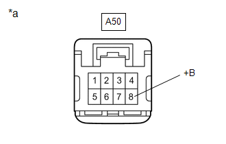
| *a | Front view of wire harness connector (to Windshield Wiper Relay Assembly) |
(a) Measure the voltage according to the value(s) in the table below.
Standard Voltage:
| Tester Connection | Condition | Specified Condition |
|---|---|---|
| A50-8 (+B) - Body ground | Ignition switch ON | 11 to 14 V |
| Less than approximately 60 seconds after ignition switch turned off | 11 to 14 V | |
| Approximately 60 seconds or more after ignition switch turned off | Below 1 V |
| OK |
| REPLACE WINDSHIELD WIPER RELAY ASSEMBLY |
|
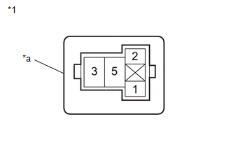
| 7. | INSPECT WIPER RELAY |
Click here
| NG |
| REPLACE WIPER RELAY |
|
| 8. | CHECK HARNESS AND CONNECTOR (POWER SOURCE - WIPER RELAY) |
| (a) Measure the voltage according to the value(s) in the table below. Standard Voltage:
|
|
| NG |
| REPAIR OR REPLACE HARNESS OR CONNECTOR |
|
| 9. | CHECK HARNESS AND CONNECTOR (WINDSHIELD WIPER RELAY ASSEMBLY - WIPER RELAY) |
(a) Measure the resistance according to the value(s) in the table below.
Standard Resistance:
| Tester Connection | Condition | Specified Condition |
|---|---|---|
| A50-8 (+B) - WIPER relay holder terminal 5 | Always | Below 1 Ω |
| A50-8 (+B) - Body ground | Always | 10 kΩ or higher |
| OK |
| REPLACE MAIN BODY ECU (MULTIPLEX NETWORK BODY ECU) |
| NG |
| REPAIR OR REPLACE HARNESS OR CONNECTOR |
| 10. | INSPECT WIPER RELAY |
Click here
| NG |
| REPLACE WIPER RELAY |
|
| 11. | CHECK HARNESS AND CONNECTOR (WIPER RELAY - MAIN BODY ECU (MULTIPLEX NETWORK BODY ECU)) |
(a) Disconnect the H4 main body ECU (multiplex network body ECU) connector.
(b) Measure the resistance according to the value(s) in the table below.
Standard Resistance:
| Tester Connection | Condition | Specified Condition |
|---|---|---|
| WIPER relay holder terminal 1 - H4-6 (WPS) | Always | Below 1 Ω |
| WIPER relay holder terminal 1 or H4-6 (WPS) - Body ground | Always | 10 kΩ or higher |
| NG |
| REPAIR OR REPLACE HARNESS OR CONNECTOR |
|
| 12. | CHECK HARNESS AND CONNECTOR (BODY GROUND - WIPER RELAY) |
| (a) Measure the voltage according to the value(s) in the table below. Standard Resistance:
|
|
| OK |
| REPLACE MAIN BODY ECU (MULTIPLEX NETWORK BODY ECU) |
| NG |
| REPAIR OR REPLACE HARNESS OR CONNECTOR |
 Rain Sensor Malfunction (B1400)
DESCRIPTION This DTC is stored when the rain sensor detects an internal malfunction. DTC No. Detection Item DTC Detection Condition Trouble Area Memory DTC Output from B1400 Rain Sensor Malfunction
IG power source voltage is 9...
 Front Wiper Motor Circuit
DESCRIPTION The windshield wiper relay assembly controls the windshield wiper motor assembly through this circuit. WIRING DIAGRAM
PROCEDURE 1. PERFORM ACTIVE TEST USING GTS (FRONT WIPER LO OPERATION / FRONT WIPER HI OPERATION) (a) Perform the Active Test according to the display on the GTS...
Other information:
Toyota Yaris XP210 (2020-2026) Owner's Manual: Hill Launch Assist (HLA)(If equipped)
Hill Launch Assist (HLA) is a function which assists the driver in accelerating from a stop while on a slope. When the driver releases the brake pedal and depresses the accelerator pedal while on a slope, the function prevents the vehicle from rolling...
Toyota Yaris XP210 (2020-2026) Reapir and Service Manual: Intake Air Temperature Sensor 1 Bank 1 Circuit Short to Ground (P011011)
DESCRIPTION The intake air temperature sensor, mounted on the mass air flow meter sub-assembly, monitors the intake air temperature. The intake air temperature sensor has a built-in thermistor with a resistance that varies according to the temperature of the intake air...
Categories
- Manuals Home
- Toyota Yaris Owners Manual
- Toyota Yaris Service Manual
- Key Battery Replacement
- G16e-gts (engine Mechanical)
- Engine Start Function When Key Battery is Dead
- New on site
- Most important about car
Turning the Engine Off
Stop the vehicle completely. Manual transaxle: Shift into neutral and set the parking brake.Automatic transaxle: Shift the selector lever to the P position and set the parking brake.
Press the push button start to turn off the engine. The ignition position is off.