Toyota Yaris: Smart Key System (for Entry Function) / Front Passenger Side Door Entry Lock Function does not Operate
DESCRIPTION
If the entry lock function does not operate for the front passenger door only, but the entry unlock function operates, the request code is being transmitted properly from the for passenger door. In this case, there may be a problem related to the lock sensor (connection between the certification ECU (smart key ECU assembly) and front door outside handle assembly RH).
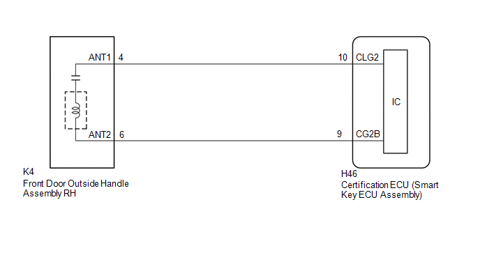
WIRING DIAGRAM
CAUTION / NOTICE / HINT
NOTICE:
- When using the GTS with the ignition switch off, connect the GTS to the DLC3 and turn a courtesy light switch on and off at intervals of 1.5 seconds or less until communication between the GTS and the vehicle begins. Then select the vehicle type under manual mode and enter the following menus: Body Electrical / Smart Key. While using the GTS, periodically turn a courtesy light switch on and off at intervals of 1.5 seconds or less to maintain communication between the GTS and the vehicle.
-
The smart key system (for Entry Function) uses the CAN communication system. Inspect the communication function by following How to Proceed with Troubleshooting. Troubleshoot the smart key system (for Entry Function) after confirming that the communication systems are functioning properly.
Click here

-
Before replacing the certification ECU (smart key ECU assembly), refer to Precaution.
Click here

- After repair, confirm that no DTCs are output.
- Check that there are no electrical key transmitter sub-assemblies in the vehicle.
PROCEDURE
| 1. | CHECK POWER DOOR LOCK CONTROL SYSTEM |
(a) When the door control switch on the multiplex network master switch assembly is operated, check that the doors unlock and lock according to the switch operation.
Click here

OK:
Door locks operate normally.
| NG |
 | GO TO POWER DOOR LOCK CONTROL SYSTEM |
|

| 2. | CHECK ENTRY OPERATION |
(a) Check that the entry lock function.
| (1) Turn the ignition switch off. |
|
(2) Open and close the front passenger door.
(3) Hold the electrical key transmitter sub-assembly at the same height as the door outside handle assembly RH and approximately 0.3 m (0.984 ft.) from the front passenger door.
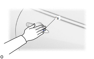
(4) Touch the lock sensor of the front door outside handle assembly RH (groove on the front door outside handle) with 2 or more fingers for 2 seconds or more.
HINT:
- If the door does not lock even when touching the lock sensor for 2 seconds or more, touch it with your palm.
- When checking the operation of the lock sensor again, make sure to perform the procedure from step (1).
- When checking the operation of the entry lock function several times, it can be operated up to 2 times consecutively. To operate the function 3 times or more consecutively, the doors need to be unlocked once. However, this is only for the entry lock function, other door lock operations, such as a wireless door lock operation can be performed consecutively.
| Result | Proceed to |
|---|---|
| Entry function does not operate normally | A |
| Entry function operates normally | B |
| B |
 | GO TO CHECK FOR INTERMITTENT PROBLEMS (OPERATION HISTORY) |
|

| 3. | READ VALUE USING GTS (PASSENGER SIDE LOCK SENSOR) |
| (a) Open and close the front passenger door. |
|

(b) Hold the electrical key transmitter sub-assembly at the same height as the door outside handle assembly RH and approximately 0.3 m (0.984 ft.) from the front passenger door.
(c) Read the Data List according to the display on the GTS.
(d) Touch the lock sensor of the front door outside handle assembly RH (groove on the front door outside handle) with 2 or more fingers for 2 seconds or more.
HINT:
- If the door does not lock even when touching the lock sensor for 2 seconds or more, touch it with your palm.
- When checking the operation of the lock sensor again, make sure to perform the procedure from step (a).
- When checking the operation of the entry lock function several times, it can be operated up to 2 times consecutively. To operate the function 3 times or more consecutively, the doors need to be unlocked once. However, this is only for the entry lock function, other door lock operations, such as a wireless door lock operation can be performed consecutively.
| Tester Display | Measurement Item | Range | Normal Condition | Diagnostic Note |
|---|---|---|---|---|
| Passenger Side Lock Sensor | Front passenger door touch sensor (lock sensor) | OFF or ON | OFF: Front passenger door touch sensor (lock sensor) not touched ON: Front passenger door touch sensor (lock sensor) touched |
|
| Tester Display |
|---|
| Passenger Side Lock Sensor |
OK:
The GTS display changes correctly in response to the operation of the front door outside handle assembly RH.
| OK |
 | REPLACE CERTIFICATION ECU (SMART KEY ECU ASSEMBLY) |
|

| 4. | CHECK HARNESS AND CONNECTOR (CERTIFICATION ECU (SMART KEY ECU ASSEMBLY) - FRONT DOOR OUTSIDE HANDLE ASSEMBLY RH) |
(a) Disconnect the H46 certification ECU (smart key ECU assembly) connector.
(b) Disconnect the K4 front door outside handle assembly RH connector.
(c) Measure the resistance according to the value(s) in the table below.
Standard Resistance:
| Tester Connection | Condition | Specified Condition |
|---|---|---|
| H46-10 (CLG2) - K4-4 (ANT1) | Always | Below 1 Ω |
| H46-9 (CG2B) - K4-6 (ANT2) | Always | Below 1 Ω |
| H46-10 (CLG2) or K4-4 (ANT1) - Other terminals and body ground | Always | 10 kΩ or higher |
| H46-9 (CG2B) or K4-6 (ANT2) - Other terminals and body ground | Always | 10 kΩ or higher |
(d) Reconnect the K4 front door outside handle assembly RH connector.
(e) Reconnect the H46 certification ECU (smart key ECU assembly) connector.
| NG |
 | REPAIR OR REPLACE HARNESS OR CONNECTOR |
|

| 5. | READ VALUE USING GTS (PASSENGER SIDE LOCK SENSOR) |
| (a) Open and close the front passenger door. |
|

(b) Hold the electrical key transmitter sub-assembly at the same height as the door outside handle assembly RH and approximately 0.3 m (0.984 ft.) from the front passenger door.
(c) Read the Data List according to the display on the GTS.
(d) Touch the lock sensor of the front door outside handle assembly RH (groove on the front door outside handle) with 2 or more fingers for 2 seconds or more.
HINT:
- If the door does not lock even when touching the lock sensor for 2 seconds or more, touch it with your palm.
- When checking the operation of the lock sensor again, make sure to perform the procedure from step (a).
- When checking the operation of the entry lock function several times, it can be operated up to 2 times consecutively. To operate the function 3 times or more consecutively, the doors need to be unlocked once. However, this is only for the entry lock function, other door lock operations, such as a wireless door lock operation can be performed consecutively.
| Tester Display | Measurement Item | Range | Normal Condition | Diagnostic Note |
|---|---|---|---|---|
| Passenger Side Lock Sensor | Front passenger door touch sensor (lock sensor) | OFF or ON | OFF: Front passenger door touch sensor (lock sensor) not touched ON: Front passenger door touch sensor (lock sensor) touched |
|
| Tester Display |
|---|
| Passenger Side Lock Sensor |
OK:
The GTS display changes correctly in response to the operation of the front door outside handle assembly RH.
| OK |
 | END (CONNECTOR WAS NOT CONNECTED SECURELY) |
| NG |
 | REPLACE FRONT DOOR OUTSIDE HANDLE ASSEMBLY RH |
 Driver Side Door Entry Lock Function does not Operate
DESCRIPTION If the entry lock function does not operate for the driver door only, but the entry unlock function operates, the request code is being transmitted properly from the driver door...
 Entry Interior Alarm does not Sound
DESCRIPTION The smart key system (for Entry Function) uses the buzzer in the combination meter assembly (meter ECU) to perform various vehicle interior warnings...
Other information:
Toyota Yaris XP210 (2020-2026) Reapir and Service Manual: Vehicle Speed Sensor "A" No Signal (P050031)
DESCRIPTION Vehicles, which are equipped with ABS (Anti-lock Brake System), detect the vehicle speed using the skid control ECU (brake actuator assembly) and speed sensor. The speed sensor monitors the wheel rotation speed and sends a signal to the skid control ECU...
Toyota Yaris XP210 (2020-2026) Reapir and Service Manual: Reassembly
REASSEMBLY PROCEDURE 1. INSTALL STARTER CENTER BEARING CLUTCH SUB-ASSEMBLY (a) Apply high-temperature grease to the pinion drive lever as shown in the illustration. *1 Starter Center Bearing Clutch Sub-assembly *2 Starter Drive Housing Assembly *3 Pinion Drive Lever *4 Rubber Seal High-temperature Grease (b) Install the pinion drive lever and rubber seal to the starter center bearing clutch sub-assembly...
Categories
- Manuals Home
- Toyota Yaris Owners Manual
- Toyota Yaris Service Manual
- Key Battery Replacement
- Brake System Control Module "A" System Voltage System Voltage Low (C137BA2)
- Engine & Hybrid System
- New on site
- Most important about car
Key Suspend Function
If a key is left in the vehicle, the functions of the key left in the vehicle are temporarily suspended to prevent theft of the vehicle.
To restore the functions, press the unlock button on the functions-suspended key in the vehicle.