Toyota Yaris: Starter / Reassembly
REASSEMBLY
PROCEDURE
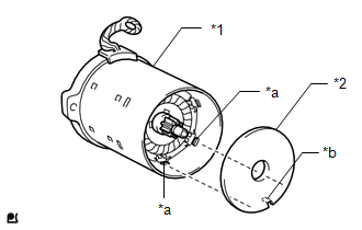
1. INSTALL STARTER CENTER BEARING CLUTCH SUB-ASSEMBLY
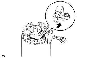
(a) Apply high-temperature grease to the pinion drive lever as shown in the illustration.
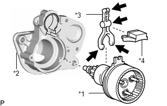
| *1 | Starter Center Bearing Clutch Sub-assembly |
| *2 | Starter Drive Housing Assembly |
| *3 | Pinion Drive Lever |
| *4 | Rubber Seal |
 | High-temperature Grease |
(b) Install the pinion drive lever and rubber seal to the starter center bearing clutch sub-assembly.
(c) Install the starter center bearing clutch sub-assembly together with the pinion drive lever and rubber seal to the starter drive housing assembly.
2. INSTALL PLANETARY GEAR
(a) Apply high-temperature grease to the 3 planetary gears, 3 planetary gear shafts and starter center bearing clutch sub-assembly.
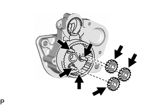
 | High-temperature Grease |
(b) Install the 3 planetary gears to the starter center bearing clutch sub-assembly.
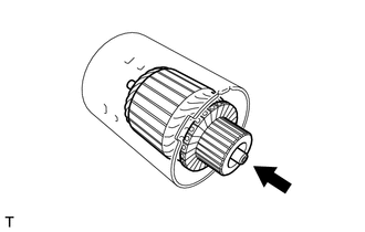
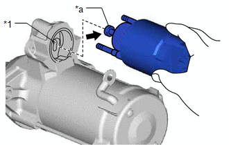
3. INSTALL STARTER ARMATURE ASSEMBLY
| (a) Install the starter armature assembly to the starter yoke assembly. NOTICE: The magnet of the starter yoke assembly may attract the starter armature assembly when the starter armature assembly is installed, causing the magnet to break. |
|
4. INSTALL STARTER BRUSH HOLDER ASSEMBLY
| (a) Hold the brush spring back and set the 4 brushes as shown in the illustration. |
|
| (b) Install the starter brush holder assembly to the starter armature assembly and push in the 4 brushes as shown in the illustration. |
|
| (c) Fit the protrusion of the grommet between the negative (-) brush holder plate and positive (+) motor lead wire. |
|
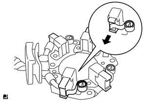
5. INSTALL STARTER COMMUTATOR END FRAME ASSEMBLY
| (a) Install the starter commutator end frame assembly to the starter yoke assembly. NOTICE: Align the field coil lead wire rubber of the starter yoke assembly with the cutout of the starter commutator end frame assembly. |
|
| (b) Install the 2 screws. Torque: 1.5 N·m {15 kgf·cm, 13 in·lbf} |
|
6. INSTALL STARTER ARMATURE PLATE
| (a) Align the starter armature plate so that the protrusion fits between the stoppers of the starter yoke assembly, and install the starter armature plate. NOTICE: Make sure the protrusion of the starter armature plate is inserted between the stoppers of the starter yoke assembly. |
|
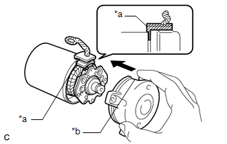
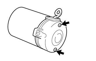
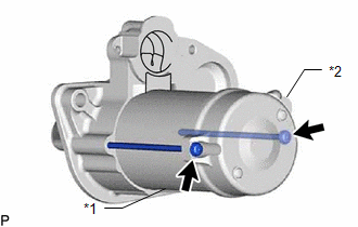
7. INSTALL STARTER YOKE ASSEMBLY
| (a) Align the protrusion of the starter yoke assembly with the cutout of the starter drive housing assembly. |
|
| (b) Using a T25 "TORX" socket wrench, install the 2 through bolts. Torque: 6.0 N·m {61 kgf·cm, 53 in·lbf} |
|
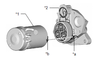
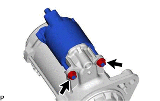
8. INSTALL MAGNET STARTER SWITCH ASSEMBLY
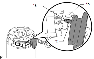
(a) Apply high-temperature grease to the magnet starter switch assembly as shown in the illustration.
| *1 | Pinion Drive Lever |
| *a | Hook |
 | High-temperature Grease |
(b) Hang the hook of the magnet starter switch assembly on the pinion drive lever.
| (c) Install the magnet starter switch assembly with the 2 nuts. Torque: 7.5 N·m {76 kgf·cm, 66 in·lbf} |
|
9. INSTALL STARTER INRUSH CURRENT REDUCTION RELAY
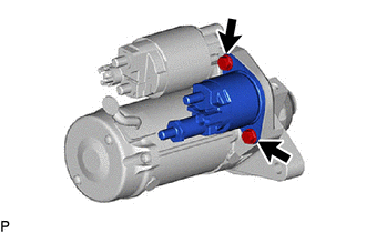
(a) Install the starter inrush current reduction relay to the starter drive housing assembly with the 2 bolts.
Torque:
7.9 N·m {81 kgf·cm, 70 in·lbf}
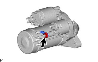
| (b) Connect the field coil lead wire to the starter inrush current reduction relay with the nut. Torque: 9.0 N·m {92 kgf·cm, 80 in·lbf} |
|
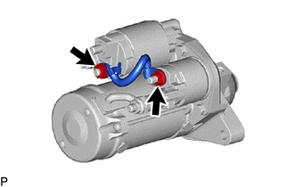
10. INSTALL WIRE HARNESS
| (a) Install the wire harness to the starter assembly with the 2 nuts. Torque: 6.5 N·m {66 kgf·cm, 58 in·lbf} |
|
 Inspection
INSPECTION PROCEDURE 1. INSPECT STARTER ASSEMBLY CAUTION: As a large electric current passes through the cable during this inspection, a thick cable must be used...
 Installation
INSTALLATION PROCEDURE 1. INSTALL STARTER ASSEMBLY (a) Install the wire harness clamp bracket to the starter assembly with the bolt. Torque: 10 N·m {102 kgf·cm, 7 ft·lbf} (b) Install the starter assembly to the cylinder block sub-assembly with the 2 bolts...
Other information:
Toyota Yaris XP210 (2020-2026) Reapir and Service Manual: Inspection
INSPECTION PROCEDURE 1. INSPECT FRONT SEAT INNER BELT ASSEMBLY (for Driver Side) (a) Check the resistance. (1) Measure the resistance according to the value(s) in the table below. Standard Resistance: Tester Connection Condition Specified Condition If the result is not as specified, replace the front seat inner belt assembly...
Toyota Yaris XP210 (2020-2026) Reapir and Service Manual: Components
C..
Categories
- Manuals Home
- Toyota Yaris Owners Manual
- Toyota Yaris Service Manual
- Engine Start Function When Key Battery is Dead
- Key Battery Replacement
- Power Integration No.1 System Missing Message (B235287,B235587,B235787-B235987)
- New on site
- Most important about car
Turning the Engine Off
Stop the vehicle completely. Manual transaxle: Shift into neutral and set the parking brake.Automatic transaxle: Shift the selector lever to the P position and set the parking brake.
Press the push button start to turn off the engine. The ignition position is off.