Toyota Yaris: Starter / Installation
INSTALLATION
PROCEDURE
1. INSTALL STARTER ASSEMBLY
(a) Install the wire harness clamp bracket to the starter assembly with the bolt.
Torque:
10 N·m {102 kgf·cm, 7 ft·lbf}
(b) Install the starter assembly to the cylinder block sub-assembly with the 2 bolts.
Torque:
46 N·m {469 kgf·cm, 34 ft·lbf}
(c) Connect the engine wire to terminal 30 with the nut.
Torque:
9.8 N·m {100 kgf·cm, 87 in·lbf}
(d) Connect the clamp.
(e) Close the terminal cap.
(f) Connect the 2 starter assembly connectors.
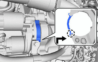
2. INSTALL FLYWHEEL HOUSING SIDE COVER
| (a) Align the protrusion with the cylinder block sub-assembly and attach the claw as shown in the illustration to install the flywheel housing side cover. NOTICE:
|
|
3. INSTALL OIL COOLER ASSEMBLY
(a) Install 2 new oil cooler gaskets to the oil cooler assembly.
(b) Install the oil cooler assembly to the cylinder block sub-assembly with the 2 nuts and bolt.
Torque:
21 N·m {214 kgf·cm, 15 ft·lbf}
4. CONNECT NO. 5 WATER BY-PASS HOSE
(a) Connect the No. 5 water by-pass hose to the oil cooler assembly, and slide the clip to secure them.
5. CONNECT NO. 6 WATER BY-PASS HOSE
(a) Connect the No. 6 water by-pass hose to the oil cooler assembly, and slide the clip to secure them.
6. INSTALL NO. 1 ENGINE UNDER COVER ASSEMBLY
Click here

7. CONNECT CABLE TO NEGATIVE AUXILIARY BATTERY TERMINAL
Click here

8. INITIALIZATION AFTER RECONNECTING AUXILIARY BATTERY TERMINAL
HINT:
When disconnecting and reconnecting the auxiliary battery, there is an automatic learning function thatcompletes learning when the respective system is used.
Click here

 Reassembly
REASSEMBLY PROCEDURE 1. INSTALL STARTER CENTER BEARING CLUTCH SUB-ASSEMBLY (a) Apply high-temperature grease to the pinion drive lever as shown in the illustration...
 Starting System
Parts LocationPARTS LOCATION ILLUSTRATION
*1 STARTER ASSEMBLY *2 ECM *3 NO. 1 ENGINE ROOM RELAY BLOCK AND JUNCTION BLOCK ASSEMBLY - ST NO...
Other information:
Toyota Yaris XP210 (2020-2026) Reapir and Service Manual: Removal
REMOVAL CAUTION / NOTICE / HINT The necessary procedures (adjustment, calibration, initialization or registration) that must be performed after parts are removed and installed, or replaced during the windshield glass removal/installation are shown below...
Toyota Yaris XP210 (2020-2026) Reapir and Service Manual: Actuator Supply Voltage "A" Circuit Short to Ground or Open (P065714)
DESCRIPTION The electronic throttle control system has a dedicated power supply circuit. The voltage (+BM, +BM2) is monitored and when it is low (less than 4 V), the ECM determines that there is a malfunction in the electronic throttle control system and cuts off the current to the throttle actuator...
Categories
- Manuals Home
- Toyota Yaris Owners Manual
- Toyota Yaris Service Manual
- To Set Speed
- How to connect USB port/Auxiliary jack
- Battery Monitor Module General Electrical Failure (P058A01)
- New on site
- Most important about car
Front Seat Belt Pretensioners
The front seat belt pretensioners are designed to deploy in moderate or severe frontal, near frontal collisions.
In addition, the pretensioners operate when a side collision or a rollover accident is detected. The pretensioners operate differently depending on what types of air bags are equipped. For more details about the seat belt pretensioner operation, refer to the SRS Air Bag Deployment Criteria.