Toyota Yaris: Starter / Inspection
INSPECTION
PROCEDURE
1. INSPECT STARTER ASSEMBLY
CAUTION:
As a large electric current passes through the cable during this inspection, a thick cable must be used. If not, the cable may become hot and cause injury.
NOTICE:
Perform each of the following tests within 3 to 5 seconds to prevent the coil from burning out.
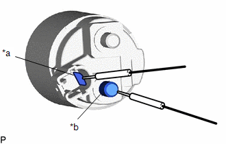
(a) Perform a pull-in test.
(1) Connect a battery to the magnet starter switch assembly as shown in the illustration. Check that the clutch pinion gear moves outward.
If the clutch pinion gear does not move outward, replace the magnet starter switch assembly.
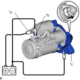
| *a | Terminal 50 |
| *b | Terminal C |
| *c | Starter Body |
 | Moves outward |
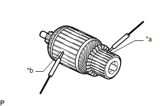
(b) Perform a hold-in test.
(1) While maintaining the battery connections of the pull-in test, disconnect the negative (-) lead from terminal C. Check that the clutch pinion gear does not return inward.
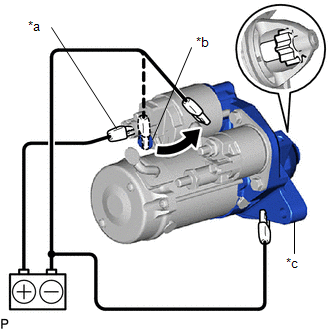
| *a | Terminal 50 |
| *b | Terminal C |
| *c | Starter Body |
 | Disconnect |
If the clutch pinion gear returns inward, replace the magnet starter switch assembly.
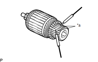
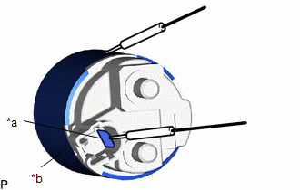
(c) Perform a return test.
(1) Disconnect the negative (-) lead from the starter body. Check that the clutch pinion gear returns inward.
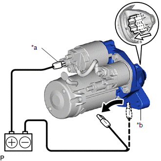
| *a | Terminal 50 |
| *b | Starter Body |
 | Disconnect |
 | Returns inward |
If the clutch pinion gear does not return inward, replace the magnet starter switch assembly.
(d) Perform a no-load performance test.
(1) Secure the starter assembly in a vise between aluminum plates.
NOTICE:
Ensure that the starter assembly is secured in the vise to prevent it from falling out.
(2) Connect the battery and an ammeter to the starter assembly as shown in the illustration.
NOTICE:
Do not allow any lead to get caught as the clutch pinion gear operates.
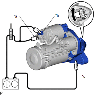
| *a | Terminal 50 |
| *b | Terminal 30 |
| *c | Starter Body |
 | Rotates |
(3) Check that the starter assembly operates smoothly and steadily while the clutch pinion gear is moving outward.
Measure the current according to the value(s) in the table below.
Standard Current:
| Tester Connection | Condition | Specified Condition |
|---|---|---|
| Battery positive (+) terminal - Terminal 30 - Terminal 50 | 11.5 V | Below 100 A |
If the result is not as specified, replace the starter assembly.
2. INSPECT STARTER ARMATURE ASSEMBLY
HINT:
If there is no continuity between any segments, replace the starter armature assembly.
(a) Check the commutator appearance.
If the surface is dirty or burnt, replace the starter armature assembly.
| (b) Check the commutator for an open circuit. (1) Measure the resistance according to the value(s) in the table below. Standard Resistance:
If the result is not as specified, replace the starter armature assembly. |
|
| (c) Check the commutator for a short circuit. (1) Measure the resistance according to the value(s) in the table below. Standard Resistance:
If the result is not as specified, replace the starter armature assembly. |
|
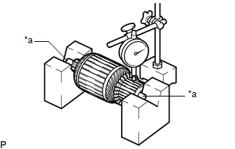
| (d) Check the commutator for runout. (1) Place the armature shaft on V-blocks. (2) Using a dial indicator, measure the runout. Maximum Runout: 0.05 mm (0.00197 in.) If the runout is greater than the maximum, replace the starter armature assembly. |
|
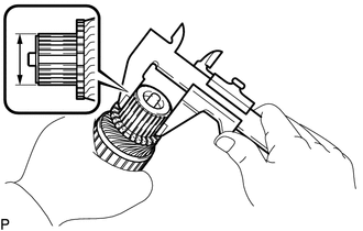
| (e) Using a vernier caliper, measure the commutator diameter. Standard Diameter: 29 mm (1.1417 in.) Minimum Diameter: 28 mm (1.1024 in.) If the diameter is less than the minimum, replace the starter armature assembly. |
|
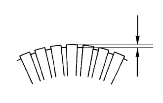
| (f) Check that the undercut portion between the segments is free of foreign matter and measure its depth. Standard Undercut Depth: 0.7 mm (0.0276 in.) Minimum Undercut Depth: 0.4 mm (0.0157 in.) If the undercut depth is less than the minimum, replace the starter armature assembly. |
|
3. INSPECT STARTER BRUSH HOLDER ASSEMBLY
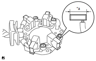
| (a) Check the brush length. (1) Using a vernier caliper, measure the brush length. Standard Length: 14.4 mm (0.567 in.) Minimum Length: 9.0 mm (0.354 in.) If the length is less than the minimum, replace the starter brush holder assembly. |
|
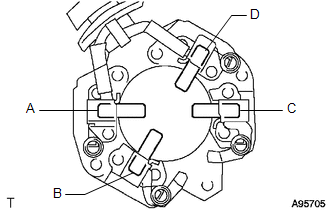
| (b) Check the brush holder resistance. (1) Measure the resistance according to the value(s) in the table below. Standard Resistance:
If the result is not as specified, replace the starter brush holder assembly. |
|
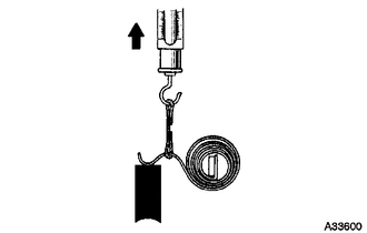
(c) Check the brush spring load.
| (1) Take a pull scale reading the instant the brush spring separates from the brush. Standard Spring Load: 16.2 to 19.8 N (1.65 to 2.02 kgf, 3.64 to 4.45 lbf) Minimum Spring Load: 6.7 N (0.68 kgf, 1.5 lbf) If the spring load is less than the minimum, replace the starter brush holder assembly. |
|
4. INSPECT STARTER CLUTCH
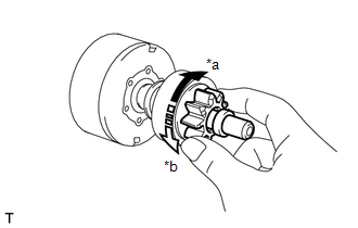
| *a | Free |
| *b | Lock |
(a) Check the clutch pinion gear.
(1) Rotate the clutch pinion gear clockwise and check that it turns freely. Try to rotate the clutch pinion gear counterclockwise and check that it locks.
If the clutch pinion gear does not operate as specified, replace the starter center bearing clutch sub-assembly.
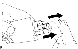
5. INSPECT MAGNET STARTER SWITCH ASSEMBLY
| (a) Check the plunger. (1) Push in the plunger and check that it returns quickly to its original position. If the plunger does not operate as specified, replace the magnet starter switch assembly. |
|
| (b) Check the pull-in coil for an open circuit. (1) Measure the resistance according to the value(s) in the table below. Standard Resistance:
If the result is not as specified, replace the magnet starter switch assembly. |
|
| (c) Check the holding coil for an open circuit. (1) Measure the resistance according to the value(s) in the table below. Standard Resistance:
If the result is not as specified, replace the magnet starter switch assembly. |
|
 Disassembly
DISASSEMBLY PROCEDURE 1. REMOVE WIRE HARNESS (a) Remove the 2 nuts and wire harness from the starter assembly.
2. REMOVE STARTER INRUSH CURRENT REDUCTION RELAY (a) Remove the bolt and wire harness from the starter inrush current reduction relay...
 Reassembly
REASSEMBLY PROCEDURE 1. INSTALL STARTER CENTER BEARING CLUTCH SUB-ASSEMBLY (a) Apply high-temperature grease to the pinion drive lever as shown in the illustration...
Other information:
Toyota Yaris XP210 (2020-2026) Reapir and Service Manual: Backup Boost Converter Circuit
DESCRIPTION A backup boost converter is built into the engine stop and start ECU. The backup boost converter helps maintain the power source voltage when the engine is restarted by stop and start control. This prevents various functions such as the audio and visual system from malfunctioning if the power source voltage drops due to the auxiliary battery voltage dropping when the engine is restarted by stop and start control...
Toyota Yaris XP210 (2020-2026) Reapir and Service Manual: Installation
INSTALLATION PROCEDURE 1. INSTALL TRANSFER AND TRANSAXLE SETTING STUD BOLT Click here 2. INSTALL TRANSFER ASSEMBLY (a) Clean the bolt holes. (b) Using SST and union nut wrench, install the transfer assembly to the transaxle with the 6 nuts and 2 bolts...
Categories
- Manuals Home
- Toyota Yaris Owners Manual
- Toyota Yaris Service Manual
- Battery Monitor Module General Electrical Failure (P058A01)
- Key Battery Replacement
- G16e-gts (engine Mechanical)
- New on site
- Most important about car
Supplemental Restraint System (SRS) Precautions
The front and side supplemental restraint systems (SRS) include different types of air bags. Please verify the different types of air bags which are equipped on your vehicle by locating the “SRS AIRBAG” location indicators. These indicators are visible in the area where the air bags are installed.
The air bags are installed in the following locations:
The steering wheel hub (driver air bag) The front passenger dashboard (front passenger air bag) The outboard sides of the front seatbacks (side air bags) The front and rear window pillars, and the roof edge along both sides (curtain air bags)