Toyota Yaris: Transfer Assembly / Installation
INSTALLATION
PROCEDURE
1. INSTALL TRANSFER AND TRANSAXLE SETTING STUD BOLT
Click here

2. INSTALL TRANSFER ASSEMBLY
(a) Clean the bolt holes.
(b) Using SST and union nut wrench, install the transfer assembly to the transaxle with the 6 nuts and 2 bolts.
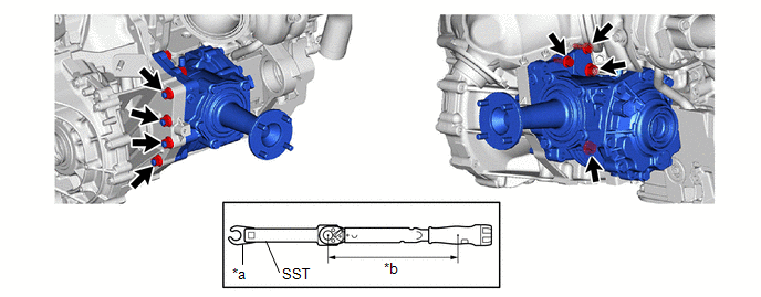
| *a | Union Nut Wrench | *b | Torque Wrench Fulcrum Length |
Torque:
Specified tightening torque :
68.6 N·m {700 kgf·cm, 51 ft·lbf}
SST: 09961-00950
HINT:
-
Calculate the torque wrench reading when changing the fulcrum length of the torque wrench.
Click here

- When using a union nut wrench (fulcrum length of 30 mm (1.181 in.)) + SST (fulcrum length of 150 mm (5.906 in.)) + torque wrench (fulcrum length of 255 mm (10.039 in.)): 40.2 N*m (410 kgf*cm, 30 ft.*lbf)
3. INSTALL MANUAL TRANSAXLE ASSEMBLY
Click here

 Reassembly
REASSEMBLY CAUTION / NOTICE / HINT NOTICE: Steps 9 to 16 are temporary reassembly procedures for adjustment purposes. PROCEDURE 1. INSTALL TRANSFER RING GEAR MOUNTING CASE (a) Using SST and a press, press the transfer ring gear mounting case into the transfer ring gear...

Other information:
Toyota Yaris XP210 (2020-2026) Reapir and Service Manual: Components
COMPONENTS ILLUSTRATION *1 DECK BOARD ASSEMBLY *2 FUSIBLE LINK COVER *3 POSITIVE AUXILIARY BATTERY TERMINAL *4 BATTERY CLAMP SUB-ASSEMBLY *5 NEGATIVE AUXILIARY BATTERY TERMINAL *6 BATTERY HOSE *7 AUXILIARY BATTERY - - Tightening torque for "Major areas involving basic vehicle performance such as moving/turning/stopping": N*m (kgf*cm, ft...
Toyota Yaris XP210 (2020-2026) Reapir and Service Manual: Problem Symptoms Table
PROBLEM SYMPTOMS TABLE HINT: Use the table below to help determine the cause of problem symptoms. If multiple suspected areas are listed, the potential causes of the symptoms are listed in order of probability in the "Suspected Area" column of the table...
Categories
- Manuals Home
- Toyota Yaris Owners Manual
- Toyota Yaris Service Manual
- G16e-gts (engine Mechanical)
- Maintenance
- Engine Start Function When Key Battery is Dead
- New on site
- Most important about car
Supplemental Restraint System (SRS) Precautions
The front and side supplemental restraint systems (SRS) include different types of air bags. Please verify the different types of air bags which are equipped on your vehicle by locating the “SRS AIRBAG” location indicators. These indicators are visible in the area where the air bags are installed.
The air bags are installed in the following locations:
The steering wheel hub (driver air bag) The front passenger dashboard (front passenger air bag) The outboard sides of the front seatbacks (side air bags) The front and rear window pillars, and the roof edge along both sides (curtain air bags)