Toyota Yaris: Theft Deterrent / Keyless Entry / Electrical Key Oscillator (for Rear Floor)
Components
COMPONENTS
ILLUSTRATION
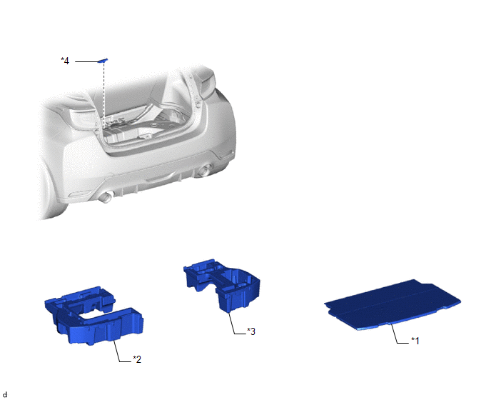
| *1 | DECK BOARD ASSEMBLY | *2 | DECK FLOOR BOX LH |
| *3 | DECK FLOOR BOX RH | *4 | NO. 2 INDOOR ELECTRICAL KEYANTENNA ASSEMBLY |
Removal
REMOVAL
PROCEDURE
1. REMOVE DECK BOARD ASSEMBLY
Click here

2. REMOVE DECK FLOOR BOX RH
Click here

3. REMOVE DECK FLOOR BOX LH
Click here

4. REMOVE NO. 2 INDOOR ELECTRICAL KEY ANTENNA ASSEMBLY
| (a) Disconnect the connector. |
|
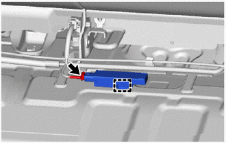
(b) Using a clip remover,disengage the clamp to remove the No. 2 indoor electrical key antenna assembly.
NOTICE:
Be careful when installing the No. 2 indoor electrical key antenna assembly. If the No. 2 indoor electrical key antenna assembly is dropped, replace it with a new one.
Installation
INSTALLATION
PROCEDURE
1. INSTALL NO. 2 INDOOR ELECTRICAL KEY ANTENNA ASSEMBLY
| (a) Engage the clamp to install the No. 2 indoor electrical key antenna assembly. NOTICE: Be careful when installing the No. 2 indoor electrical key antenna assembly. If the No. 2 indoor electrical key antenna assembly is dropped, replace it with a new one. |
|

(b) Connect the connector.
2. INSTALL DECK FLOOR BOX LH
Click here

3. INSTALL DECK FLOOR BOX RH
Click here

4. INSTALL DECK BOARD ASSEMBLY
Click here

 Electrical Key Oscillator (for Outside Luggage Compartment)
ComponentsCOMPONENTS ILLUSTRATION
*1 ELECTRICAL KEY ANTENNA - -
N*m (kgf*cm, ft.*lbf): Specified torque - - RemovalREMOVAL PROCEDURE 1...
 Engine Hood Courtesy Switch
ComponentsCOMPONENTS ILLUSTRATION
*1 ENGINE HOOD COURTESY SWITCH (HOOD LOCK ASSEMBLY) - -
N*m (kgf*cm, ft.*lbf): Specified torque
MP grease RemovalREMOVAL PROCEDURE 1...
Other information:
Toyota Yaris XP210 (2020-2026) Owner's Manual: Declaration of Conformity
K..
Toyota Yaris XP210 (2020-2026) Reapir and Service Manual: Active Noise Control Microphone
ComponentsCOMPONENTS ILLUSTRATION *1 ACTIVE NOISE CONTROL MICROPHONE - - RemovalREMOVAL CAUTION / NOTICE / HINT HINT: When the cable is disconnected / reconnected to the auxiliary battery terminal, systems temporarily stop operating. However, each system has a function that completes learning the first time the system is used...
Categories
- Manuals Home
- Toyota Yaris Owners Manual
- Toyota Yaris Service Manual
- Immobilizer System
- Headlights
- Adjustment
- New on site
- Most important about car
Supplemental Restraint System (SRS) Precautions
The front and side supplemental restraint systems (SRS) include different types of air bags. Please verify the different types of air bags which are equipped on your vehicle by locating the “SRS AIRBAG” location indicators. These indicators are visible in the area where the air bags are installed.
The air bags are installed in the following locations:
The steering wheel hub (driver air bag) The front passenger dashboard (front passenger air bag) The outboard sides of the front seatbacks (side air bags) The front and rear window pillars, and the roof edge along both sides (curtain air bags)