Toyota Yaris: Theft Deterrent / Keyless Entry / Engine Hood Courtesy Switch
Components
COMPONENTS
ILLUSTRATION
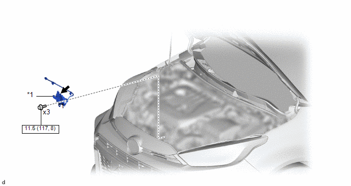
| *1 | ENGINE HOOD COURTESY SWITCH (HOOD LOCK ASSEMBLY) | - | - |
 | N*m (kgf*cm, ft.*lbf): Specified torque |
 | MP grease |
Removal
REMOVAL
PROCEDURE
1. REMOVE ENGINE HOOD COURTESY SWITCH (HOOD LOCK ASSEMBLY)
| (a) Disconnect the connector. |
|
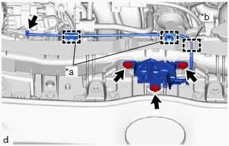
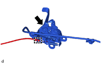
(b) Disengage the clamps and guide
(c) Remove the 3 bolts.
| (d) Disengage the guide to disconnect the hood lock control cable assembly, and remove the engine hood courtesy switch (hood lock assembly) |
|
Inspection
INSPECTION
PROCEDURE
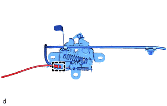
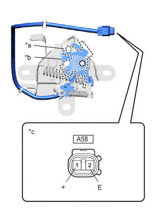
1. INSPECT ENGINE HOOD COURTESY SWITCH (HOOD LOCK ASSEMBLY)
| (a) Check the resistance. (1) Measure the resistance according to the value(s) in the table below. Standard Resistance:
If the result is not as specified, replace the engine hood courtesy switch (hood lock assembly). |
|
Installation
INSTALLATION
PROCEDURE
1. INSTALL NGINE HOOD COURTESY SWITCH (HOOD LOCK ASSEMBLY)
| (a) Apply MP grease to the sliding parts of the engine hood courtesy switch (hood lock assembly). |
|
(b) Engage the guide to connect the hood lock control cable assembly.
| (c) Engage the guide and clamps. |
|

(d) Connect the connector.
(e) Install the engine hood courtesy switch (hood lock assembly) with the 3 bolts.
Torque:
11.5 N·m {117 kgf·cm, 8 ft·lbf}
2. INSPECT HOOD SUB-ASSEMBLY
Click here

3. ADJUST HOOD SUB-ASSEMBLY
Click here

 Electrical Key Oscillator (for Rear Floor)
ComponentsCOMPONENTS ILLUSTRATION
*1 DECK BOARD ASSEMBLY *2 DECK FLOOR BOX LH *3 DECK FLOOR BOX RH *4 NO. 2 INDOOR ELECTRICAL KEYANTENNA ASSEMBLY RemovalREMOVAL PROCEDURE 1...
 Id Code Box
ComponentsCOMPONENTS ILLUSTRATION
*1 ID CODE BOX (IMMOBILISER CODE ECU) - - RemovalREMOVAL CAUTION / NOTICE / HINT The necessary procedures (adjustment, calibration, initialization, or registration) that must be performed after parts are removed, installed, or replaced during the ID code box (immobiliser code ECU) removal/installation are shown below...
Other information:
Toyota Yaris XP210 (2020-2026) Reapir and Service Manual: Stop Lamp Relay Actuator Stuck On (C13807E)
DESCRIPTION When any of the following conditions are met, the skid control ECU (brake actuator assembly) sets the drive output (STPO) ON which operates the stop light switch assembly and turns on the stop lights. Illumination Conditions: Pre-collision brake is operating...
Toyota Yaris XP210 (2020-2026) Reapir and Service Manual: Installation
INSTALLATION CAUTION / NOTICE / HINT NOTICE: After performing the update ECU security key procedure, make sure to perform the initialization procedure for when the cable has been disconnected and reconnected to the negative (-) auxiliary battery terminal...
Categories
- Manuals Home
- Toyota Yaris Owners Manual
- Toyota Yaris Service Manual
- Fuse Panel Description
- Engine Start Function When Key Battery is Dead
- G16e-gts (engine Mechanical)
- New on site
- Most important about car
Turning the Engine Off
Stop the vehicle completely. Manual transaxle: Shift into neutral and set the parking brake.Automatic transaxle: Shift the selector lever to the P position and set the parking brake.
Press the push button start to turn off the engine. The ignition position is off.