Toyota Yaris: Theft Deterrent / Keyless Entry / Id Code Box
Components
COMPONENTS
ILLUSTRATION
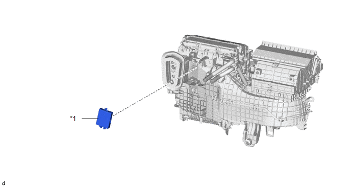
| *1 | ID CODE BOX (IMMOBILISER CODE ECU) | - | - |
Removal
REMOVAL
CAUTION / NOTICE / HINT
The necessary procedures (adjustment, calibration, initialization, or registration) that must be performed after parts are removed, installed, or replaced during the ID code box (immobiliser code ECU) removal/installation are shown below.
Necessary Procedure After Parts Removed/Installed/Replaced| Replacement Part or Procedure | Necessary Procedures | Effects / Inoperative when not performed | Link |
|---|---|---|---|
| ID code box (immobiliser code ECU) | Code registration |
|
|

PROCEDURE
1. REMOVE AIR CONDITIONER UNIT ASSEMBLY
Click here

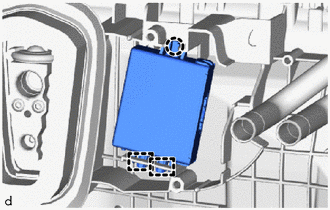
2. REMOVE ID CODE BOX (IMMOBILISER CODE ECU)
| (a) Disengage the claw and 2 guides to remove the ID code box (immobiliser code ECU). NOTICE: Do not reuse dropped or damaged parts. |
|
Installation
INSTALLATION
CAUTION / NOTICE / HINT
NOTICE:
Before replacing the ID code box (immobiliser code ECU), refer to Registration.
Click here

PROCEDURE
1. INSTALL ID CODE BOX (IMMOBILISER CODE ECU)
(a) Engage the claw and 2 guides to install the ID code box (immobiliser code ECU).
NOTICE:
Do not reuse dropped or damaged parts.
2. INSTALL AIR CONDITIONER UNIT ASSEMBLY
Click here

 Engine Hood Courtesy Switch
ComponentsCOMPONENTS ILLUSTRATION
*1 ENGINE HOOD COURTESY SWITCH (HOOD LOCK ASSEMBLY) - -
N*m (kgf*cm, ft.*lbf): Specified torque
MP grease RemovalREMOVAL PROCEDURE 1...
 Security Horn Assembly
ComponentsCOMPONENTS ILLUSTRATION
*1 SECURITY HORN ASSEMBLY - -
N*m (kgf*cm, ft.*lbf): Specified torque - - InspectionINSPECTION PROCEDURE 1...
Other information:
Toyota Yaris XP210 (2020-2026) Reapir and Service Manual: Registration
REGISTRATION PROCEDURE 1. ECU EXCHANGE NOTICE: When replacing the engine stop and start ECU, make sure to download the number of starter operations (step 1). After replacing the engine stop and start ECU (step 2), write the number of starter operations to the new engine stop and start ECU (step 3)...
Toyota Yaris XP210 (2020-2026) Reapir and Service Manual: Lost Communication with Front Air Outlet Damper Control Servo Motor LIN Missing Message (B140287)
DESCRIPTION The air conditioning harness assembly connects the air conditioning amplifier assembly and the No. 1 air conditioning radiator damper servo sub-assembly. The air conditioning amplifier assembly supplies power and sends operation instructions to No...
Categories
- Manuals Home
- Toyota Yaris Owners Manual
- Toyota Yaris Service Manual
- Power Integration No.1 System Missing Message (B235287,B235587,B235787-B235987)
- Auto Lock/Unlock Function
- To Set Speed
- New on site
- Most important about car
Front Seat Belt Pretensioners
The front seat belt pretensioners are designed to deploy in moderate or severe frontal, near frontal collisions.
In addition, the pretensioners operate when a side collision or a rollover accident is detected. The pretensioners operate differently depending on what types of air bags are equipped. For more details about the seat belt pretensioner operation, refer to the SRS Air Bag Deployment Criteria.