Toyota Yaris: Door Locks / Auto Lock/Unlock Function
- When the vehicle speed exceeds 12 mph (20 km/h), all doors and the liftgate lock automatically.
- When the ignition is switched off, all doors and the liftgate unlock automatically.
These functions can also be disabled so that they do not operate.
Auto lock/unlock function setting change using door-lock switch
The doors and the liftgate can be set to lock or unlock automatically by selecting any one of the functions from the following table and using the driver’s door-lock switch on the interior door panel.
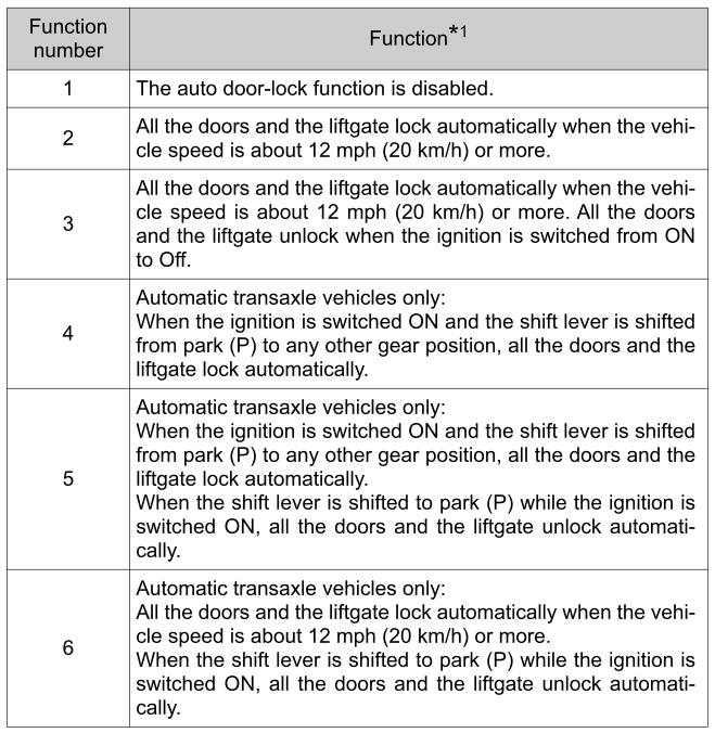
* 1: Other settings for the auto door lock function are available at your Toyota dealer. For details consult your Toyota dealer. Refer to Customizable Features.
Settings can be changed using the following procedure.
- Safely park the vehicle. All doors and the liftgate must remain closed.
- Switch the ignition ON.
- Press and hold the lock side of the driver’s door-lock switch within 20 seconds of switching the ignition ON, and make sure a beep sound is heard about eight seconds afterwards.
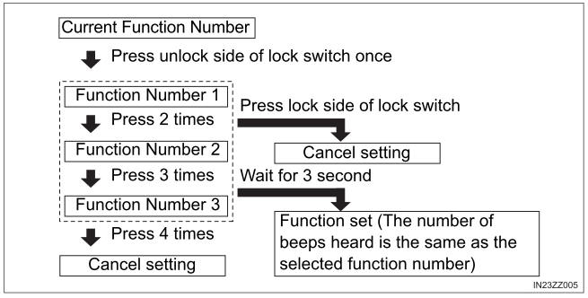
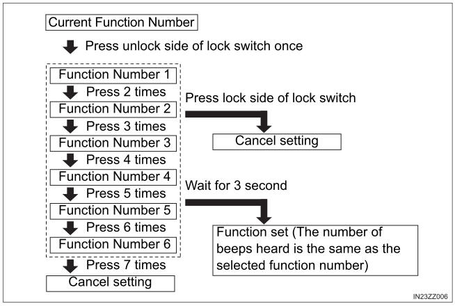
- Refer to the auto lock/unlock function setting table, determine the function number for the desired setting. Press the unlock side of the driver’s door-lock switch the same number of times as the selected function number (Ex. If you select function 2, press the unlock side of the switch only 2 times).
- Three seconds after the function setting has been changed, a beep sound will beep in the amount of the selected function number. (Ex. Function number 3 = 3 beep sounds)
Manual transaxle vehicles
Automatic transaxle vehicles
- Function number 3 is the factory setting for your vehicle.
- There are only a total of three auto lock/unlock settings available for manual transaxle vehicles, and six for automatic transaxle vehicles. Be sure to press the unlock side of the driver’s door-lock switch the correct number of times according to the selected function number. If the switch is mistakenly pressed four times on a manual transaxle vehicle or seven times on an automatic transaxle, the procedure will be cancelled. If this occurs, start the procedure from the beginning.
- The doors and the liftgate cannot be locked or unlocked while the setting function is being performed.
- The procedure can be cancelled by pressing the lock side of the driver’s door-lock switch.
WARNING
Do not pull the inner handle on a front door
Pulling the inner handle on a front door while the vehicle is moving is dangerous. Passengers can fall out of the vehicle if the door opens accidentally, which could result in death or serious injury.
 Locking, Unlocking with Smart Key and Door-Lock Switch
Locking, Unlocking with Smart Key
All doors and the liftgate can be locked/unlocked by operating the keyless entry system smart key, refer to Keyless Entry System
Locking, Unlocking with Door-Lock Switch
All doors and the liftgate lock automatically when the lock side is
pressed...
 Locking, Unlocking with Door-Lock Knob
Operation from inside
LockTo lock any door from the inside,
press the door-lock knob.
UnlockTo unlock, pull it outward.
This does not operate the other
door locks...
Other information:
Toyota Yaris XP210 (2020-2026) Reapir and Service Manual: Components
COMPONENTS ILLUSTRATION *1 TURBINE OUTLET ELBOW GASKET *2 EXHAUST PIPE CLAMP *3 EXHAUST MANIFOLD CONVERTER SUB-ASSEMBLY *4 ENGINE WIRE *5 NO. 2 CLUTCH FLEXIBLE HOSE BRACKET *6 STARTER ASSEMBLY *7 FLYWHEEL HOUSING SIDE COVER *8 ENGINE ASSEMBLY WITH TRANSAXLE Tightening torque for "Major areas involving basic vehicle performance such as moving/turning/stopping": N*m (kgf*cm, ft...
Toyota Yaris XP210 (2020-2026) Owner's Manual: How to connect USB port/Auxiliary jack
USB port Auxiliary jack Connecting a device Connect the connector on the device to the USB port. Connecting with a connector cable Connect the device plug/connector cable to the auxiliary jack/USB port. Insert the plug into the auxiliary jack/USB port securely...
Categories
- Manuals Home
- Toyota Yaris Owners Manual
- Toyota Yaris Service Manual
- Immobilizer System
- Engine & Hybrid System
- Power Integration No.1 System Missing Message (B235287,B235587,B235787-B235987)
- New on site
- Most important about car
Key Suspend Function
If a key is left in the vehicle, the functions of the key left in the vehicle are temporarily suspended to prevent theft of the vehicle.
To restore the functions, press the unlock button on the functions-suspended key in the vehicle.