Toyota Yaris: Transfer Assembly / Removal
REMOVAL
CAUTION / NOTICE / HINT
The necessary procedures (adjustment, calibration, initialization, or registration) that must be performed after parts are removed and installed, or replaced during the transfer assembly removal/installation are shown below.
HINT:
When the cable is disconnected / reconnected to the auxiliary battery terminal, systems temporarily stop operating. However, each system has a function that completes learning the first time the system is used.
-
Learning completes when vehicle is driven
Effect/Inoperative Function When Necessary Procedures are not Performed
Necessary Procedures
Link
Lane tracing assist system
Drive the vehicle straight ahead at 35 km/h (22 mph) or more for 5 second or more.

Pre-collision system
Stop and start system
Drive the vehicle until stop and start control is permitted (approximately 5 to 60 minutes)

-
Learning completes when vehicle is operated normally
Effect/Inoperative Function When Necessary Procedures are not Performed
Necessary Procedures
Link
Power door lock control system
- Back door opener
Perform door unlock operation with door control switch or electrical key transmitter sub-assembly switch.

Air conditioning system
After the ignition switch is turned to ON, the servo motor standard position is recognized.
-
PROCEDURE
1. REMOVE MANUAL TRANSAXLE ASSEMBLY
Click here

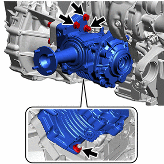
2. REMOVE TRANSFER ASSEMBLY
| (a) Remove the 4 nuts. |
|
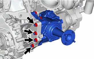
| (b) Remove the 2 bolts, 2 nuts and transfer assembly. |
|
3. REMOVE TRANSFER AND TRANSAXLE SETTING STUD BOLT
Click here

 Components
COMPONENTS ILLUSTRATION
*1 MANUAL TRANSAXLE ASSEMBLY *2 TRANSFER ASSEMBLY *3 TRANSFER AND TRANSAXLE SETTING STUD BOLT - -
Tightening torque for "Major areas involving basic vehicle performance such as moving/turning/stopping" : N*m (kgf*cm, ft...
 Disassembly
DISASSEMBLY CAUTION / NOTICE / HINT NOTICE: Before installation of each part, thoroughly clean and dry it. Then apply grease or oil as necessary. Do not use alkaline chemicals to clean aluminum parts, rubber parts or precoated bolts...
Other information:
Toyota Yaris XP210 (2020-2026) Reapir and Service Manual: Front Axle Hub Bolt
ComponentsCOMPONENTS ILLUSTRATION *1 FRONT AXLE HUB BOLT *2 FRONT DISC *3 FRONT DISC BRAKE CALIPER ASSEMBLY - - Tightening torque for "Major areas involving basic vehicle performance such as moving/turning/stopping": N*m (kgf*cm, ft...
Toyota Yaris XP210 (2020-2026) Reapir and Service Manual: Components
COMPONENTS ILLUSTRATION *1 KNOCK SENSOR *2 NO. 1 VENTILATION CASE *3 NO. 2 CYLINDER BLOCK INSULATOR *4 NO. 2 WATER BY-PASS PIPE *5 NO. 6 WATER BY-PASS HOSE *6 NO. 4 WATER BY-PASS HOSE *7 GASKET - - N*m (kgf*cm, ft...
Categories
- Manuals Home
- Toyota Yaris Owners Manual
- Toyota Yaris Service Manual
- Headlights
- Auto Lock/Unlock Function
- G16e-gts (engine Mechanical)
- New on site
- Most important about car
Fuel-Filler Lid and Cap
WARNING
When removing the fuel-filler cap, loosen the cap slightly and wait for any hissing to stop, then remove it
Fuel spray is dangerous. Fuel can burn skin and eyes and cause illness if ingested. Fuel spray is released when there is pressure in the fuel tank and the fuel-filler cap is removed too quickly.