Toyota Yaris: Sfi System / Throttle / Pedal Position Sensor / Switch "A" Circuit Short to Battery or Open (P012015)
DESCRIPTION
Refer to DTC P012011.
Click here

| DTC No. | Detection Item | DTC Detection Condition | Trouble Area | MIL | Note |
|---|---|---|---|---|---|
| P012015 | Throttle / Pedal Position Sensor / Switch "A" Circuit Short to Battery or Open | The output voltage of VTA1 is higher than 4.535 V for 2 seconds or more (1 trip detection logic). |
| Comes on | SAE: P0123 |
MONITOR DESCRIPTION
The ECM uses the throttle position sensor to monitor the throttle valve opening angle. If the VTA1 terminal voltage is higher than the threshold, the ECM will illuminate the MIL and store this DTC.
MONITOR STRATEGY
| Frequency of Operation | Continuous |
CONFIRMATION DRIVING PATTERN
- Connect the GTS to the DLC3.
- Turn the ignition switch to ON.
- Turn the GTS on.
- Clear the DTCs (even if no DTCs are stored, perform the clear DTC procedure).
- Turn the ignition switch off and wait for at least 30 seconds.
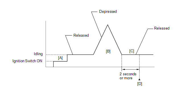
- Turn the ignition switch to ON [A].
- Turn the GTS on.
- Start the engine.
- With the vehicle stationary, fully depress and release the accelerator pedal [B].
- Idle the engine for 2 seconds or more [C].
- Enter the following menus: Powertrain / Engine / Trouble Codes [D].
-
Read the pending DTCs.
HINT:
- If a pending DTC is output, the system is malfunctioning.
- If a pending DTC is not output, perform the following procedure.
- Enter the following menus: Powertrain / Engine / Utility / All Readiness.
- Input the DTC: P012015.
-
Check the DTC judgment result.
GTS Display
Description
NORMAL
- DTC judgment completed
- System normal
ABNORMAL
- DTC judgment completed
- System abnormal
INCOMPLETE
- DTC judgment not completed
- Perform driving pattern after confirming DTC enabling conditions
HINT:
- If the judgment result is NORMAL, the system is normal.
- If the judgment result is ABNORMAL, the system is malfunctioning.
- If the judgment result is INCOMPLETE, perform steps [B] through [D] again.
FAIL-SAFE
When this DTC is stored, the ECM enters fail-safe mode. During fail-safe mode, the ECM cuts the current to the throttle actuator, and the throttle valve is returned to a 7.5° throttle valve opening angle by the return spring. The ECM then adjusts the engine output by controlling the fuel injection (intermittent fuel-cut) and ignition timing, in accordance with the accelerator pedal angle, to allow the vehicle to continue running at a minimal speed. If the accelerator pedal is depressed firmly and gently, the vehicle can be driven slowly.
Fail-safe mode continues until a pass condition is detected, and the ignition switch is turned off.
WIRING DIAGRAM
Refer to DTC P012011.
Click here

CAUTION / NOTICE / HINT
HINT:
Read Freeze Frame Data using the GTS. The ECM records vehicle and driving condition information as Freeze Frame Data the moment a DTC is stored. When troubleshooting, Freeze Frame Data can help determine if the vehicle was moving or stationary, if the engine was warmed up or not, if the air fuel ratio was lean or rich, and other data from the time the malfunction occurred.
PROCEDURE
| 1. | CHECK HARNESS AND CONNECTOR (THROTTLE POSITION SENSOR - ECM) |
(a) Disconnect the throttle body with motor assembly connector.
(b) Disconnect the ECM connector.
(c) Measure the resistance according to the value(s) in the table below.
Standard Resistance:
| Tester Connection | Condition | Specified Condition |
|---|---|---|
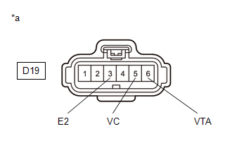
| D19-6(VTA) - D104-108(VTA1) | Always | Below 1 Ω |
| D19-3(E2) - D104-110(ETA) | Always | Below 1 Ω |
| D19-5(VC) or D104-109(VCTA) - Body ground and other terminals | Always | 10 kΩ or higher |
| D19-6(VTA) or D104-108(VTA1) - Body ground and other terminals | Always | 10 kΩ or higher |
| NG |
 | REPAIR OR REPLACE HARNESS OR CONNECTOR |
|

| 2. | CHECK TERMINAL VOLTAGE (POWER SOURCE OF THROTTLE POSITION SENSOR) |
(a) Disconnect the throttle body with motor assembly connector.
(b) Turn the ignition switch to ON.
| (c) Measure the voltage according to the value(s) in the table below. Standard Voltage:
|
|
| NG |
 | REPLACE ECM |
|

| 3. | CHECK HARNESS AND CONNECTOR (RESISTANCE OF ECM) |
(a) Disconnect the throttle body with motor assembly connector.
(b) Measure the resistance according to the value(s) in the table below.
Standard Resistance:
| Tester Connection | Condition | Specified Condition |
|---|---|---|
| D19-5(VC) - D19-6(VTA) | Ignition switch off | 190 to 210 kΩ |
| NG |
 | REPLACE ECM |
|

| 4. | READ VALUE USING GTS (THROTTLE POSITION SENSOR NO.1 VOLTAGE) |
(a) Disconnect the throttle body with motor assembly connector.
(b) According to the display on the GTS, read the Data List.
Powertrain > Engine > Data List| Tester Display |
|---|
| Throttle Position Sensor No.1 Voltage |
HINT:
Use the snapshot function to record the value displayed or make a note of it.
|

| 5. | READ VALUE USING GTS (THROTTLE POSITION SENSOR NO.1 VOLTAGE) |
(a) Connect terminals 4 (E2) and 1 (VTA) of the throttle body with motor assembly connector on the wire harness side.
NOTICE:
If the VTA terminal voltage or the resistance between VTA and E2 is abnormal and terminals 1 (VTA) and 4 (E2) of the throttle body with motor assembly connector are connected, excessive current may flow through the circuit. In this case, do not connect the terminals.
(b) Compare the vehicle of the Data List item Throttle Position Sensor No.1 Voltage after the circuit is shorted to the value when the throttle body with motor assembly connector was connected.
Powertrain > Engine > Data List| Tester Display |
|---|
| Throttle Position Sensor No.1 Voltage |
| Result | Proceed to |
|---|---|
| Changes from higher than 4.535 V to below 0.56 V | A |
| Does not change from higher than 4.535 V | B |
| A |
 | REPLACE THROTTLE BODY WITH MOTOR ASSEMBLY |
| B |
 | REPLACE ECM |
 Throttle / Pedal Position Sensor / Switch "A" Circuit Voltage Out of Range (P01201C)
DESCRIPTION Refer to DTC P012011. Click here
DTC No. Detection Item DTC Detection Condition Trouble Area MIL Note P01201C Throttle / Pedal Position Sensor / Switch "A" Circuit Voltage Out of Range The difference between the output voltage of VTA1 and VTA2 is below 0...
 Turbocharger/Supercharger Inlet Pressure Sensor "A" Circuit Low Circuit Short to Ground (P012A11)
DESCRIPTION The internal sensor in the E.F.I. vacuum sensor assembly detects the air inlet duct internal pressure as a voltage.
DTC No. Detection Item DTC Detection Condition Trouble Area MIL Note P012A11 Turbocharger/Supercharger Inlet Pressure Sensor "A" Circuit Low Circuit Short to Ground The output voltage from the E...
Other information:
Toyota Yaris XP210 (2020-2025) Reapir and Service Manual: Problem Symptoms Table
PROBLEM SYMPTOMS TABLE HINT: Use the table below to help determine the cause of problem symptoms. If multiple suspected areas are listed, the potential causes of the symptoms are listed in order of probability in the "Suspected Area" column of the table...
Toyota Yaris XP210 (2020-2025) Reapir and Service Manual: Barometric Pressure - Turbocharger / Supercharger Boost Sensor "A" Signal Compare Failure (P00CF62)
DESCRIPTION At ignition switch to ON or during idling, the No. 2 turbo pressure sensor and the atmospheric pressure sensor built into the ECM are at atmospheric pressure and their outputs match. DTC No. Detection Item DTC Detection Condition Trouble Area MIL Note P00CF62 Barometric Pressure - Turbocharger / Supercharger Boost Sensor "A" Signal Compare Failure 15 kPa [2...
Categories
- Manuals Home
- Toyota Yaris Owners Manual
- Toyota Yaris Service Manual
- To Set Speed
- Immobilizer System
- Maintenance
- New on site
- Most important about car
Front Seat Belt Pretensioners
The front seat belt pretensioners are designed to deploy in moderate or severe frontal, near frontal collisions.
In addition, the pretensioners operate when a side collision or a rollover accident is detected. The pretensioners operate differently depending on what types of air bags are equipped. For more details about the seat belt pretensioner operation, refer to the SRS Air Bag Deployment Criteria.