Toyota Yaris: Sfi System / Turbocharger/Supercharger Inlet Pressure Sensor "A" Circuit Low Circuit Short to Ground (P012A11)
DESCRIPTION
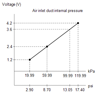
The internal sensor in the E.F.I. vacuum sensor assembly detects the air inlet duct internal pressure as a voltage.
| DTC No. | Detection Item | DTC Detection Condition | Trouble Area | MIL | Note |
|---|---|---|---|---|---|
| P012A11 | Turbocharger/Supercharger Inlet Pressure Sensor "A" Circuit Low Circuit Short to Ground | The output voltage from the E.F.I. vacuum sensor assembly is below 0.6 V for 3 seconds or more (1 trip detection logic). |
| - | SAE: P012C |
HINT:
When a DTC is output, check the Data List item "Turbocharger/Supercharger Inlet Pressure Bank1" using the GTS.
Click here

| DTC No. | Turbocharger/Supercharger Inlet Pressure Bank1 | Malfunction |
|---|---|---|
| P012A11 | Approximately 0 kPa [0 psi] |
|
If the Data List displays a normal value, the normal value may be due to a temporary recovery from the malfunction condition. Check for intermittent problems.
MONITOR DESCRIPTION
The ECM calculates the air inlet duct internal pressure from the E.F.I. vacuum sensor assembly output voltage. If the E.F.I. vacuum sensor assembly output voltage is not within the normal range, there may be a malfunction in the E.F.I. vacuum sensor assembly or an open or short circuit. In this case, the ECM stores a DTC.
Example:
When the sensor output voltage is below 0.6 V for 3 seconds or more, the ECM stores a DTC.
CONFIRMATION DRIVING PATTERN
- Connect the GTS to the DLC3.
- Turn the ignition switch to ON and turn the GTS on.
- Clear the DTCs (even if no DTCs are stored, perform the clear DTC procedure).
- Turn the ignition switch off and wait for at least 30 seconds.
- Turn the ignition switch to ON and turn the GTS on.
- Start the engine and wait 5 seconds or more.
- Enter the following menus: Powertrain / Engine / Trouble Codes.
-
Read the pending DTCs.
HINT:
- If a pending DTC is output, the system is malfunctioning.
- If a pending DTC is not output, perform the following procedure.
- Enter the following menus: Powertrain / Engine / Utility / All Readiness.
- Input the DTC: P012A11.
-
Check the DTC judgment result.
GTS Display
Description
NORMAL
- DTC judgment completed
- System normal
ABNORMAL
- DTC judgment completed
- System abnormal
INCOMPLETE
- DTC judgment not completed
- Perform driving pattern after confirming DTC enabling conditions
HINT:
- If the judgment result shows NORMAL, the system is normal.
- If the judgment result shows ABNORMAL, the system has a malfunction.
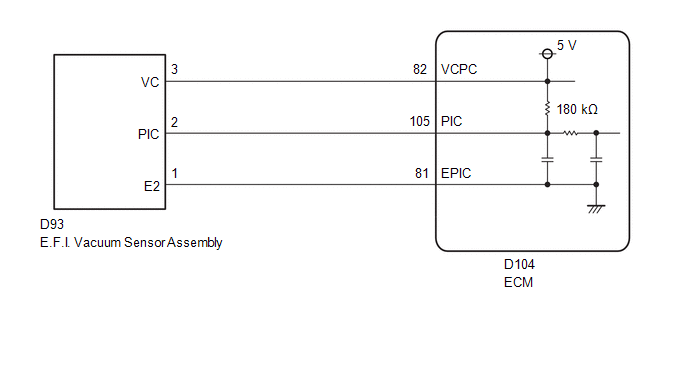
WIRING DIAGRAM
CAUTION / NOTICE / HINT
HINT:
Read Freeze Frame Data using the GTS. The ECM records vehicle and driving condition information as Freeze Frame Data the moment a DTC is stored. When troubleshooting, Freeze Frame Data can help determine if the vehicle was moving or stationary, if the engine was warmed up or not, if the air fuel ratio was lean or rich, and other data from the time the malfunction occurred.
PROCEDURE
| 1. | CHECK HARNESS AND CONNECTOR |
HINT:
Make sure that the connector is properly connected. If it is not, securely connect it and check for DTCs again.
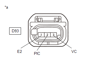
(a) Disconnect the E.F.I. vacuum sensor assembly connector.
(b) Turn the ignition switch to ON.
| (c) Measure the voltage according to the value(s) in the table below. Standard Voltage:
|
|
(d) Turn the ignition switch off and wait for at least 30 seconds.
(e) Measure the resistance according to the value(s) in the table below.
Standard Resistance:
| Tester Connection | Condition | Specified Condition |
|---|---|---|
| D93-3(VC) - D93-2(PIC) | Ignition switch off | 171 to 189 kΩ |
| OK |
 | REPLACE E.F.I. VACUUM SENSOR ASSEMBLY |
|

| 2. | CHECK HARNESS AND CONNECTOR (E.F.I. VACUUM SENSOR ASSEMBLY - ECM) |
(a) Disconnect the E.F.I. vacuum sensor assembly connector.
(b) Disconnect the ECM connector.
(c) Measure the resistance according to the value(s) in the table below.
Standard Resistance:
| Tester Connection | Condition | Specified Condition |
|---|---|---|
| D93-3(VC) - D104-82(VCPC) | Always | Below 1 Ω |
| D93-2(PIC) or D104-105(PIC) - Body ground and other terminals | Always | 10 kΩ or higher |
| OK |
 | REPLACE ECM |
| NG |
 | REPAIR OR REPLACE HARNESS OR CONNECTOR |
 Throttle / Pedal Position Sensor / Switch "A" Circuit Short to Battery or Open (P012015)
DESCRIPTION Refer to DTC P012011. Click here
DTC No. Detection Item DTC Detection Condition Trouble Area MIL Note P012015 Throttle / Pedal Position Sensor / Switch "A" Circuit Short to Battery or Open The output voltage of VTA1 is higher than 4...
 Turbocharger/Supercharger Inlet Pressure Sensor "A" Circuit High Circuit Short to Battery or Open (P012A15)
DESCRIPTION Refer to DTC P012A11. Click here
DTC No. Detection Item DTC Detection Condition Trouble Area MIL Note P012A15 Turbocharger/Supercharger Inlet Pressure Sensor "A" Circuit High Circuit Short to Battery or Open The output voltage from the E...
Other information:
Toyota Yaris XP210 (2020-2024) Reapir and Service Manual: System Description
SYSTEM DESCRIPTION DESCRIPTION The power steering system generates torque through the operation of the motor and the reduction gear installed on the column shaft in order to assist steering effort. The power steering ECU assembly determines the direction and the amount of assist power in accordance with the vehicle speed signals and signals from the torque sensor built into the electric power steering column sub-assembly...
Toyota Yaris XP210 (2020-2024) Reapir and Service Manual: Fuel Pump "A" Control Circuit Short to Ground or Open (P062714)
DESCRIPTION Refer to DTC P062712. Click here DTC No. Detection Item DTC Detection Condition Trouble Area MIL Note P062714 Fuel Pump "A" Control Circuit Short to Ground or Open When the fuel pump control ECU operation duty ratio is 3 to 65%, the FPC terminal voltage is a certain value or less for 3 seconds or more (1 trip detection logic)...
Categories
- Manuals Home
- Toyota Yaris Owners Manual
- Toyota Yaris Service Manual
- Opening and Closing the Liftgate/Trunk Lid
- Auto Lock/Unlock Function
- Immobilizer System
- New on site
- Most important about car
Keys

To use the auxiliary key, press the knob and pull out the auxiliary key from the smart key.
