Toyota Yaris: Sfi System / Turbocharger/Supercharger Inlet Pressure Sensor "A" Circuit High Circuit Short to Battery or Open (P012A15)
DESCRIPTION
Refer to DTC P012A11.
Click here

| DTC No. | Detection Item | DTC Detection Condition | Trouble Area | MIL | Note |
|---|---|---|---|---|---|
| P012A15 | Turbocharger/Supercharger Inlet Pressure Sensor "A" Circuit High Circuit Short to Battery or Open | The output voltage from the E.F.I. vacuum sensor assembly is higher than 4.9 V for 3 seconds or more (1 trip detection logic). |
| - | SAE: P012D |
HINT:
When a DTC is output, check the Data List item "Turbocharger/Supercharger Inlet Pressure Bank1" using the GTS.
Click here

| DTC No. | Turbocharger/Supercharger Inlet Pressure Bank1 | Malfunction |
|---|---|---|
| P012A15 | 120 kPa [17.4 psi] or higher |
|
If the Data List displays a normal value, the normal value may be due to a temporary recovery from the malfunction condition. Check for intermittent problems.
MONITOR DESCRIPTION
The ECM calculates the air inlet duct internal pressure from the E.F.I. vacuum sensor assembly output voltage. If the E.F.I. vacuum sensor assembly output voltage is not within the normal range, there may be a malfunction in the E.F.I. vacuum sensor assembly or an open or short circuit. In this case, the ECM stores a DTC.
Example:
When the sensor output voltage is higher than 4.9 V for 3 seconds or more, the ECM stores a DTC.
CONFIRMATION DRIVING PATTERN
- Connect the GTS to the DLC3.
- Turn the ignition switch to ON and turn the GTS on.
- Clear the DTCs (even if no DTCs are stored, perform the clear DTC procedure).
- Turn the ignition switch off and wait for at least 30 seconds.
- Turn the ignition switch to ON and turn the GTS on.
- Start the engine and wait 5 seconds or more.
- Enter the following menus: Powertrain / Engine / Trouble Codes.
-
Read the pending DTCs.
HINT:
- If a pending DTC is output, the system is malfunctioning.
- If a pending DTC is not output, perform the following procedure.
- Enter the following menus: Powertrain / Engine / Utility / All Readiness.
- Input the DTC: P012A15.
-
Check the DTC judgment result.
GTS Display
Description
NORMAL
- DTC judgment completed
- System normal
ABNORMAL
- DTC judgment completed
- System abnormal
INCOMPLETE
- DTC judgment not completed
- Perform driving pattern after confirming DTC enabling conditions
HINT:
- If the judgment result shows NORMAL, the system is normal.
- If the judgment result shows ABNORMAL, the system has a malfunction.
WIRING DIAGRAM
Refer to DTC P012A11.
Click here

CAUTION / NOTICE / HINT
HINT:
Read Freeze Frame Data using the GTS. The ECM records vehicle and driving condition information as Freeze Frame Data the moment a DTC is stored. When troubleshooting, Freeze Frame Data can help determine if the vehicle was moving or stationary, if the engine was warmed up or not, if the air fuel ratio was lean or rich, and other data from the time the malfunction occurred.
PROCEDURE
| 1. | CHECK HARNESS AND CONNECTOR |
HINT:
Make sure that the connector is properly connected. If it is not, securely connect it and check for DTCs again.
(a) Disconnect the E.F.I. vacuum sensor assembly connector.
(b) Turn the ignition switch to ON.
| (c) Measure the voltage according to the value(s) in the table below. Standard Voltage:
|
|
(d) Turn the ignition switch off and wait for at least 30 seconds.
(e) Measure the resistance according to the value(s) in the table below.
Standard Resistance:
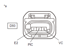
| Tester Connection | Condition | Specified Condition |
|---|---|---|
| D93-3(VC) - D93-2(PIC) | Ignition switch off | 171 to 189 kΩ |
| D93-1(E2) - Body ground | Always | Below 1 Ω |
| OK |
 | REPLACE E.F.I. VACUUM SENSOR ASSEMBLY |
|

| 2. | CHECK HARNESS AND CONNECTOR (E.F.I. VACUUM SENSOR ASSEMBLY - ECM) |
(a) Disconnect the E.F.I. vacuum sensor assembly connector.
(b) Disconnect the ECM connector.
(c) Measure the resistance according to the value(s) in the table below.
Standard Resistance:
| Tester Connection | Condition | Specified Condition |
|---|---|---|
| D93-2(PIC) - D104-105(PIC) | Always | Below 1 Ω |
| D93-1(E2) - D104-81(EPIC) | Always | Below 1 Ω |
| D93-2(PIC) or D104-105(PIC) - Other terminals | Always | 10 kΩ or higher |
| OK |
 | REPLACE ECM |
| NG |
 | REPAIR OR REPLACE HARNESS OR CONNECTOR |
 Turbocharger/Supercharger Inlet Pressure Sensor "A" Circuit Low Circuit Short to Ground (P012A11)
DESCRIPTION The internal sensor in the E.F.I. vacuum sensor assembly detects the air inlet duct internal pressure as a voltage.
DTC No. Detection Item DTC Detection Condition Trouble Area MIL Note P012A11 Turbocharger/Supercharger Inlet Pressure Sensor "A" Circuit Low Circuit Short to Ground The output voltage from the E...
 A/F (O2) Sensor Circuit Bank 1 Sensor 2 Circuit Current (Voltage) Below Threshold (P013616)
DESCRIPTION Refer to DTC P003612. Click here
DTC No. Detection Item DTC Detection Condition Trouble Area MIL Note P013616 A/F (O2) Sensor Circuit Bank 1 Sensor 2 Circuit Current (Voltage) Below Threshold Either of the following conditions is met (2 trip detection logic)...
Other information:
Toyota Yaris XP210 (2020-2026) Reapir and Service Manual: Components
COMPONENTS ILLUSTRATION *A for Front Passenger Side *B for Driver Side *C w/ Interior Illumination - - *1 FRONT DOOR LOWER FRAME BRACKET GARNISH *2 MULTIPLEX NETWORK MASTER SWITCH ASSEMBLY WITH FRONT ARMREST BASE UPPER PANEL *3 POWER WINDOW REGULATOR SWITCH ASSEMBLY WITH FRONT ARMREST BASE UPPER PANEL *4 FRONT DOOR TRIM GARNISH *5 FRONT DOOR TRIM BOARD SUB-ASSEMBLY *6 FRONT DOOR INSIDE HANDLE SUB-ASSEMBLY *7 FRONT DOOR INSIDE HANDLE BEZEL PLUG *8 FRONT DOOR GLASS INNER WEATHERSTRIP *9 NO...
Toyota Yaris XP210 (2020-2026) Reapir and Service Manual: Brake Master Cylinder Pressure Sensor Supply Voltage Circuit Short to Ground or Open (C122D14)
DESCRIPTION DTC No. Detection Item DTC Detection Condition Trouble Area DTC Output from C122D14 Brake Master Cylinder Pressure Sensor Supply Voltage Circuit Short to Ground or Open Master cylinder pressure sensor power supply voltage decrease occurs or history of voltage decrease exists, and defective master cylinder pressure sensor output continues for 1...
Categories
- Manuals Home
- Toyota Yaris Owners Manual
- Toyota Yaris Service Manual
- Battery Monitor Module General Electrical Failure (P058A01)
- Headlights
- Power Integration No.1 System Missing Message (B235287,B235587,B235787-B235987)
- New on site
- Most important about car
Liftgate/Trunk Lid
WARNING
Never allow a person to ride in the luggage compartment/trunk
Allowing a person to ride in the luggage compartment/trunk is dangerous. The person in the luggage compartment/trunk could be seriously injured or killed during sudden braking or a collision.
Do not drive with the liftgate/trunk lid open