Toyota Yaris: Sfi System / A/F (O2) Sensor Circuit Bank 1 Sensor 2 Circuit Current (Voltage) Below Threshold (P013616)
DESCRIPTION
Refer to DTC P003612.
Click here

| DTC No. | Detection Item | DTC Detection Condition | Trouble Area | MIL | Note |
|---|---|---|---|---|---|
| P013616 | A/F (O2) Sensor Circuit Bank 1 Sensor 2 Circuit Current (Voltage) Below Threshold | Either of the following conditions is met (2 trip detection logic).
|
| Comes on | SAE: P0136 |
MONITOR DESCRIPTION
Active Air fuel Ratio Control
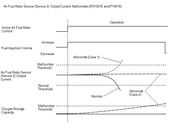
The ECM usually performs air fuel ratio feedback control so that the air fuel ratio sensors output indicates a near stoichiometric air fuel ratio. This vehicle includes active air fuel ratio control in addition to regular air fuel ratio control. The ECM performs active air fuel ratio control to detect any deterioration in the Three-Way Catalytic Converter (TWC) and any malfunctions of the air fuel ratio sensor (sensor 2) (refer to the diagram below).
Active air fuel ratio control is performed for approximately 30 seconds while driving with a warm engine. During active air fuel ratio control, the air fuel ratio is forcibly regulated to become lean or rich by the ECM. If the ECM detects a malfunction, a DTC is stored.
Abnormal Air Fuel Ratio Sensor (Sensor 2) Output Current (DTC P013616)
Case 1: The ECM illuminates the MIL and stores a DTC when active rich air-fuel ratio control is being performed and the air fuel ratio sensor (sensor 2) current is 6 mA or more.
Case 2: The ECM illuminates the MIL and stores a DTC when active rich air-fuel ratio control is being performed, the oxygen storage capacity of the catalyst is more than Threshold and the air fuel ratio sensor (sensor 2) current is -0.25757 mA or more.
MONITOR STRATEGY
| Required Sensors/Components (Main) | Air fuel ratio sensor (sensor 2) |
| Required Sensors/Components (Related) | Crankshaft position sensor Engine coolant temperature sensor Mass air flow meter sub-assembly Throttle position sensor Air fuel ratio sensor (sensor 1) |
| Frequency of Operation | Once per driving cycle |
TYPICAL ENABLING CONDITIONS
| Auxiliary battery voltage | 11 V or higher |
| Intake air temperature (mass air flow meter sub-assembly) | -10°C (14°F) or higher |
| Engine coolant temperature | 75°C (167°F) or higher |
| Atmospheric pressure | 76 kPa(abs) [11.02 psi(abs)] or higher |
| Idling | Off |
| Engine speed | Less than 3200 rpm |
| Air fuel ratio sensor (sensor 1) status | Activated |
| Fuel system status | Closed loop |
| Engine load | 10% or higher, and less than 140% |
TYPICAL MALFUNCTION THRESHOLDS
| Both of the following conditions are met | A and B |
| A. Continuous time of active rich air fuel ratio control*1 | 0.5 seconds or more |
| *1: Target air fuel ratio | 14.3 or less |
| B. Either of the following conditions is met | (a) or (b) |
| (a) Air fuel ratio sensor (sensor 2) current | 6 mA or more |
| (b) OSC (Oxygen Storage Capacity) of catalyst | More than 1.35 g |
CONFIRMATION DRIVING PATTERN
HINT:
- This confirmation driving pattern is used for the "Perform Confirmation Driving Pattern" procedure of the following diagnostic troubleshooting procedure.
- Performing this confirmation driving pattern will activate the air fuel ratio sensor (sensor 2) monitor (the catalyst monitor is performed simultaneously). This is very useful for verifying the completion of a repair.
- Connect the GTS to the DLC3.
- Turn the ignition switch to ON.
- Turn the GTS on.
- Clear the DTCs (even if no DTCs are stored, perform the clear DTC procedure).
- Turn the ignition switch off and wait for at least 30 seconds.
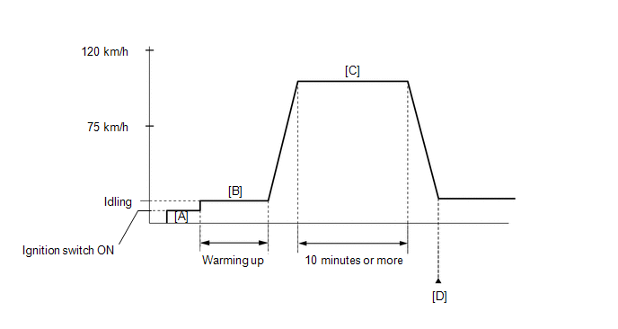
- Turn the ignition switch to ON [A].
- Turn the GTS on.
- Start the engine and warm it up until the engine coolant temperature is 75°C (167°F) or higher [B].
-
Drive the vehicle at 75 to 120 km/h (46 to 75 mph) for 10 minutes or more [C].
CAUTION:
When performing the confirmation driving pattern, obey all speed limits and traffic laws.
- Enter the following menus: Powertrain / Engine / Trouble Codes [D].
-
Read the pending DTCs.
HINT:
- If a pending DTC is output, the system is malfunctioning.
- If a pending DTC is not output, perform the following procedure.
- Enter the following menus: Powertrain / Engine / Utility / All Readiness.
- Input the DTC: P013616.
-
Check the DTC judgment result.
GTS Display
Description
NORMAL
- DTC judgment completed
- System normal
ABNORMAL
- DTC judgment completed
- System abnormal
INCOMPLETE
- DTC judgment not completed
- Perform driving pattern after confirming DTC enabling conditions
HINT:
- If the judgment result is NORMAL, the system is normal.
- If the judgment result is ABNORMAL, the system is malfunctioning.
- If the judgment result is INCOMPLETE, perform steps [C] through [D] again.
WIRING DIAGRAM
Refer to DTC P003612.
Click here

CAUTION / NOTICE / HINT
HINT:
Malfunctioning areas can be identified by performing the Active Test "Control the Injection Volume for A/F Sensor". This Active Test can help to determine whether the air fuel ratio sensors (sensor 1 and sensor 2) and other potential trouble areas are malfunctioning.
The following procedure describes how to perform the Active Test "Control the Injection Volume for A/F Sensor" using the GTS.
- Connect the GTS to the DLC3.
- Turn the ignition switch to ON.
- Turn the GTS on.
- Start the engine and warm it up until the engine coolant temperature is 75°C (167°F) or higher.
- Warm up the air fuel ratio sensors at an engine speed of 2500 rpm for 90 seconds.
- Enter the following menus: Powertrain / Engine / Active Test / Control the Injection Volume for A/F Sensor / Data List / A/F (O2) Sensor Current B1S1 and A/F (O2) Sensor Current B1S2.
- Perform the Active Test with the engine idling (change the fuel injection volume).
- Monitor the output current of the air fuel ratio sensor (sensor 1) (A/F (O2) Sensor Current B1S1) and air fuel ratio sensor (sensor 2) (A/F (O2) Sensor Current B1S2) displayed on the GTS.
HINT:
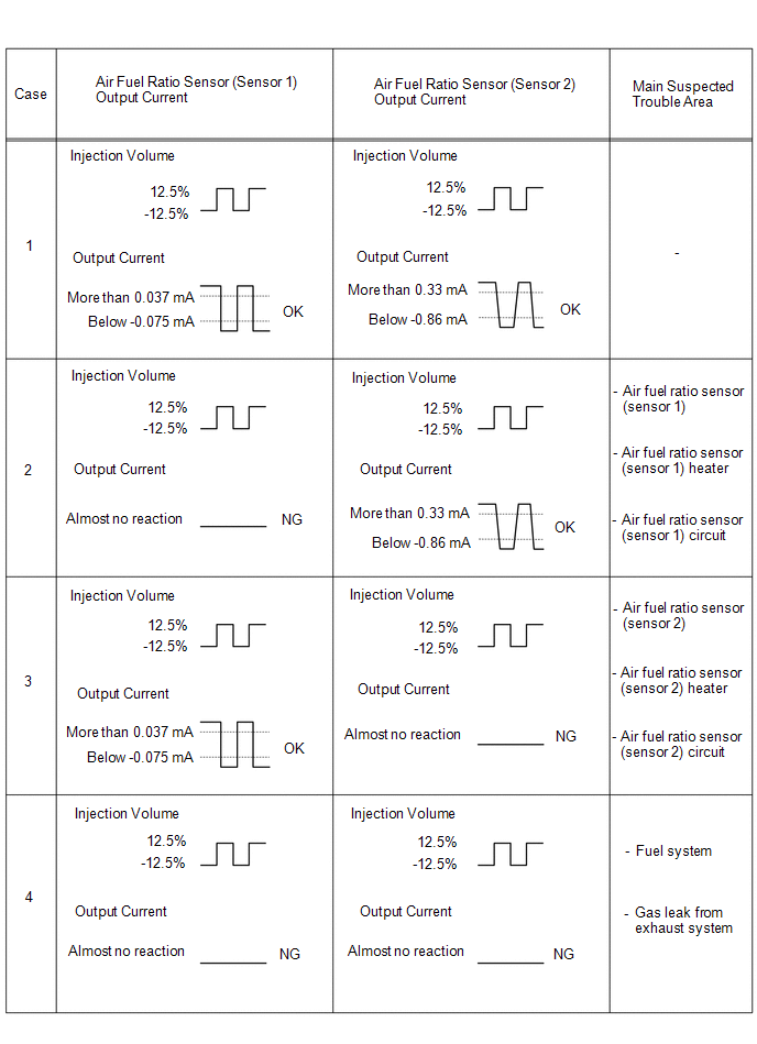
- The Active Test "Control the Injection Volume for A/F Sensor" can be used to lower the fuel injection volume by 12.5% or increase the injection volume by 12.5%.
- Each sensor reacts in accordance with the increase and decrease in the fuel injection volume.
| GTS Display (Sensor) | Injection Volume | Status | Current |
|---|---|---|---|
| A/F (O2) Sensor Current B1S1 (Air fuel ratio sensor (sensor 1)) | 12.5% | Rich | Below -0.075 mA |
| -12.5% | Lean | More than 0.037 mA | |
| A/F (O2) Sensor Current B1S2 (Air fuel ratio sensor (sensor 2)) | 12.5% | Rich | Below -0.86 mA |
| -12.5% | Lean | More than 0.33 mA |
NOTICE:
The air fuel ratio sensor (sensor 1) has an output delay for a few seconds and the air fuel ratio sensor (sensor 2) has a maximum output delay of approximately 20 seconds.
Performing the Active Test "Control the Injection Volume for A/F Sensor" allows the output value of the air fuel ratio sensors (sensor 1 and sensor 2) to be checked and graphed.
NOTICE:
Inspect the fuses for circuits related to this system before performing the following procedure.
HINT:
- Read Freeze Frame Data using the GTS. The ECM records vehicle and driving condition information as Freeze Frame Data the moment a DTC is stored. When troubleshooting, Freeze Frame Data can help determine if the vehicle was moving or stationary, if the engine was warmed up or not, if the air fuel ratio was lean or rich, and other data from the time the malfunction occurred.
- Sensor 1 refers to the sensor closest to the engine assembly.
- Sensor 2 refers to the sensor farthest away from the engine assembly.
PROCEDURE
| 1. | READ OUTPUT DTC (DTC P013616) |
(a) Read the DTCs.
Powertrain > Engine > Trouble Codes| Result | Proceed to |
|---|---|
| P013616 is output | A |
| P013616 and other DTCs are output | B |
HINT:
If any DTCs other than P013616 are output, troubleshoot those DTCs first.
| B |
 | GO TO DTC CHART |
|

| 2. | PERFORM ACTIVE TEST USING GTS (CONTROL THE INJECTION VOLUME FOR A/F SENSOR) |
(a) Start the engine and warm it up until the engine coolant temperature reaches 75°C (167°F) or higher.
(b) Warm up the air fuel ratio sensors at an engine speed of 2500 rpm for 90 seconds.
(c) Enter the following menus.
Powertrain > Engine > Active Test| Active Test Display |
|---|
| Control the Injection Volume for A/F Sensor |
| Data List Display |
|---|
| A/F (O2) Sensor Current B1S1 |
| A/F (O2) Sensor Current B1S2 |
(d) Perform the Control the Injection Volume for A/F Sensor operation with the engine idling.
(e) Monitor the output values of the air fuel ratio sensor (sensor 1) and air fuel ratio sensor (sensor 2) (A/F (O2) Sensor Current B1S1 and A/F (O2) Sensor Current B1S2) displayed on the GTS.
HINT:
- The Control the Injection Volume for A/F Sensor operation lowers the fuel injection volume by 12.5% or increases the injection volume by 12.5%.
- The air fuel ratio sensor (sensor 1) has an output delay of a few seconds and the air fuel ratio sensor (sensor 2) has a maximum output delay of approximately 20 seconds.
- If the sensor output value does not change (almost no reaction) while performing the Active Test, the sensor may be malfunctioning.
- With V type engines, when the sensor output values for both banks stay as either lean or rich, parts other than the sensor may be malfunctioning. Comparing the sensor output for both banks can be useful when troubleshooting.
| GTS Display (Sensor) | Injection Volume | Status | Current |
|---|---|---|---|
| A/F (O2) Sensor Current B1S1 (Air fuel ratio (sensor 1)) | 12.5% | Rich | Below -0.075 mA |
| -12.5% | Lean | More than 0.037 mA | |
| A/F (O2) Sensor Current B1S2 (Air fuel ratio (sensor 2)) | 12.5% | Rich | Below -0.86 mA |
| -12.5% | Lean | More than 0.33 mA |
| Status of A/F (O2) Sensor Current B1S1 | Status of A/F (O2) Sensor Current B1S2 | Suspected Trouble Area | Proceed to |
|---|---|---|---|
| Lean/Rich | Lean/Rich |
| A |
| Lean | Lean |
| B |
| Rich | Rich |
| |
| Lean/Rich | Lean |
| C |
| Lean/Rich | Rich |
| |
| Lean | Lean/Rich |
| D |
| Rich | Lean/Rich |
|
- Lean: During the Control the Injection Volume for A/F Sensor Active Test, the air fuel ratio sensor (sensor 1) output current (A/F (O2) Sensor Current B1S1 is consistently more than 0.037 mA, and the air fuel ratio sensor (sensor 2) output current (A/F (O2) Sensor Current B1S2 is consistently more than 0.33 mA.
- Rich: During the Control the Injection Volume for A/F Sensor Active Test, the air fuel ratio sensor (sensor 1) output current (A/F (O2) Sensor Current B1S1 is consistently below -0.075 mA, and the air fuel ratio sensor (sensor 2) output current (A/F (O2) Sensor Current B1S2 is consistently below -0.86 mA.
- Lean/Rich: During the Control the Injection Volume for A/F Sensor Active Test, the output current of the air fuel ratio sensor (sensor 1) or air fuel ratio sensor (sensor 2) alternate correctly.
HINT:
Refer to "Data List / Active Test" [A/F (O2) Sensor Current B1S1 and A/F (O2) Sensor Current B1S2].
Click here

| B |
 | GO TO STEP 6 |
| C |
 | GO TO STEP 8 |
| D |
 | GO TO STEP 9 |
|

| 3. | REPLACE AIR FUEL RATIO SENSOR (SENSOR 2) |
Click here

HINT:
Perform "Inspection After Repair" after replacing the air fuel ratio sensor (sensor 2).
Click here

|

| 4. | CLEAR DTC |
(a) Clear the DTCs.
Powertrain > Engine > Clear DTCs(b) Turn the ignition switch off and wait for at least 30 seconds.
|

| 5. | CONFIRM WHETHER MALFUNCTION HAS BEEN SUCCESSFULLY REPAIRED |
(a) Drive the vehicle in accordance with the driving pattern described in Confirmation Driving Pattern.
(b) Enter the following menus.
Powertrain > Engine > Utility| Tester Display |
|---|
| All Readiness |
(c) Input the DTC: P013616.
(d) Check the DTC judgment result.
Result| GTS Display | Description |
|---|---|
| NORMAL |
|
| ABNORMAL |
|
| INCOMPLETE |
|
| NEXT |
 | END |
| 6. | CHECK FOR EXHAUST GAS LEAK |
(a) Check for exhaust gas leaks.
OK:
No gas leaks in exhaust system.
HINT:
Perform "Inspection After Repair" after repairing or replacing the exhaust system.
Click here

| NG |
 | REPAIR OR REPLACE EXHAUST SYSTEM |
|

| 7. | CHECK CAUSE OF EXTREMELY RICH OR LEAN ACTUAL AIR FUEL RATIO |
(a) Check the cause of extremely rich or lean actual air fuel ratio, referring to the DTC P017100 and P017200 Inspection Procedure.
Click here

| NEXT |
 | GO TO STEP 10 |
| 8. | CHECK FOR EXHAUST GAS LEAK |
(a) Check for exhaust gas leaks.
OK:
No gas leaks in exhaust system.
HINT:
-
Perform "Inspection After Repair" after repairing or replacing the exhaust system.
Click here

-
Perform "Inspection After Repair" after replacing the air fuel ratio sensor (sensor 2).
Click here

| OK |
 | REPLACE AIR FUEL RATIO SENSOR (SENSOR 2) |
| NG |
 | REPAIR OR REPLACE EXHAUST SYSTEM |
| 9. | REPLACE AIR FUEL RATIO SENSOR (SENSOR 1) |
Click here

HINT:
Perform "Inspection After Repair" after replacing the air fuel ratio sensor (sensor 1).
Click here

|

| 10. | CLEAR DTC |
(a) Clear the DTCs.
Powertrain > Engine > Clear DTCs(b) Turn the ignition switch off and wait for at least 30 seconds.
|

| 11. | CHECK WHETHER DTC OUTPUT RECURS (DTC P013616) |
(a) Drive the vehicle in accordance with the driving pattern described in Confirmation Driving Pattern.
(b) Enter the following menus.
Powertrain > Engine > Utility| Tester Display |
|---|
| All Readiness |
(c) Input the DTC: P013616.
(d) Check that the DTC judgment result is NORMAL. If the DTC judgment result is INCOMPLETE, perform the confirmation drive pattern again but increase the vehicle speed.
| Result | Proceed to |
|---|---|
| NORMAL (DTCs are not output) | A |
| ABNORMAL (P013616 is output) | B |
HINT:
Perform "Inspection After Repair" after replacing the air fuel ratio sensor (sensor 2).
Click here

| A |
 | END |
| B |
 | REPLACE AIR FUEL RATIO SENSOR (SENSOR 2) |
 Turbocharger/Supercharger Inlet Pressure Sensor "A" Circuit High Circuit Short to Battery or Open (P012A15)
DESCRIPTION Refer to DTC P012A11. Click here
DTC No. Detection Item DTC Detection Condition Trouble Area MIL Note P012A15 Turbocharger/Supercharger Inlet Pressure Sensor "A" Circuit High Circuit Short to Battery or Open The output voltage from the E...
 System Too Lean Bank 1 (P017100,P017200,P117000,P117B00)
DESCRIPTION The fuel trim is related to the feedback compensation value, not to the basic injection duration. The fuel trim consists of both the short-term and long-term fuel trims...
Other information:
Toyota Yaris XP210 (2020-2025) Reapir and Service Manual: Installation
INSTALLATION PROCEDURE 1. INSTALL WATER INLET WITH THERMOSTAT SUB-ASSEMBLY Click here 2. INSTALL WATER INLET WITH WATER PUMP HOUSING SUB-ASSEMBLY (a) Install a new gasket to the water inlet with water pump housing sub-assembly. HINT: Be sure to clean the contact surfaces...
Toyota Yaris XP210 (2020-2025) Reapir and Service Manual: System Diagram
SYSTEM DIAGRAM Communication Table Transmitting ECU / Parts (Transmitter) Receiving ECU / Parts (Receiver) Signal Communication Method Front Airbag Sensor Airbag Sensor Assembly Front collision G signal Direct line No...
Categories
- Manuals Home
- Toyota Yaris Owners Manual
- Toyota Yaris Service Manual
- G16e-gts (engine Mechanical)
- Maintenance
- Fuse Panel Description
- New on site
- Most important about car
Refueling
Before refueling, close all the doors, windows, and the liftgate/trunk lid, and switch the ignition OFF.
To open the fuel-filler lid, pull the remote fuel-filler lid release.
