Toyota Yaris: Sfi System / System Too Lean Bank 1 (P017100,P017200,P117000,P117B00)
DESCRIPTION
The fuel trim is related to the feedback compensation value, not to the basic injection duration. The fuel trim consists of both the short-term and long-term fuel trims.
The short-term fuel trim is fuel compensation that is used to constantly maintain the air fuel ratio at stoichiometric levels. The signal from the air fuel ratio sensor (sensor 1) indicates whether the air fuel ratio is rich or lean compared to the stoichiometric ratio. This triggers a reduction in the fuel injection volume if the air fuel ratio is rich and an increase in the fuel injection volume if lean.
Factors such as individual engine differences, wear over time and changes in operating environment cause short-term fuel trim to vary from the central value. The long-term fuel trim, which controls overall fuel compensation, compensates for long-term deviations in the fuel trim from the central value caused by the short-term fuel trim compensation.
| DTC No. | Detection Item | DTC Detection Condition | Trouble Area | MIL | Note |
|---|---|---|---|---|---|
| P017100 | System Too Lean Bank 1 | With a warm engine and stable air fuel ratio feedback, the fuel trim is considerably in error to the lean side (2 trip detection logic). |
| Comes on | SAE: P0171 |
| P017200 | System Too Rich Bank 1 | With a warm engine and stable air fuel ratio feedback, the fuel trim is considerably in error to the rich side (2 trip detection logic). |
| Comes on | SAE: P0172 |
| P117000 | Fuel Performance/Port Injector | Although a DTC is stored for a rich or lean condition, the amount of fuel trim during direct injection is normal (1 trip detection logic) |
| - | SAE: P1170 |
| P117B00 | Fuel Performance/Direct Injector | Although a DTC is stored for a rich or lean condition, the amount of fuel trim during port injection is normal (1 trip detection logic) |
| - | SAE: P117B |
HINT:
- When DTC P017100 is stored, the actual air fuel ratio is on the lean side. When DTC P017200 is stored, the actual air fuel ratio is on the rich side.
- If the vehicle runs out of fuel, the air fuel ratio is lean and DTC P017100 may be stored. The MIL is then illuminated.
- When DTC P117000 or P117B00 is output, it may not be possible to precisely determine whether the port injection or the direct injection is malfunctioning, depending on the conditions. In this case, perform an Active Test (Control the Injection Mode) to determine which injection system is malfunctioning.
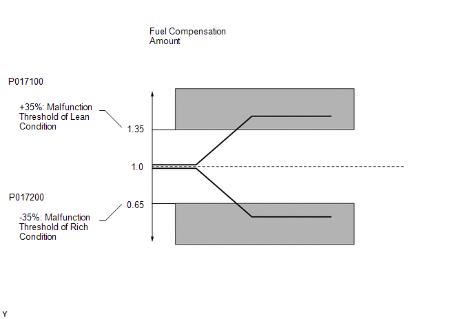
MONITOR DESCRIPTION
Under closed loop fuel control, fuel injection volumes that deviate from those estimated by the ECM cause changes in the long-term fuel trim compensation value. The long-term fuel trim is adjusted when there are persistent deviations in the short-term fuel trim values. Deviations from the fuel injection volumes estimated by the ECM also affect the average fuel trim learned value, which is a combination of the average short-term fuel trim (fuel feedback compensation value) and the average long-term fuel trim (learned value of the air fuel ratio). If the average fuel trim learned value exceeds the malfunction thresholds, the ECM interprets this as a malfunction of the fuel system and stores a DTC.
Example:
The average fuel trim learned value is +35% or higher, or -35% or less, the ECM interprets this as a fuel system malfunction.
MONITOR STRATEGY
| Required Sensors/Components (Main) | Fuel system |
| Required Sensors/Components (Related) | Air fuel ratio sensor (sensor 1) Mass air flow meter sub-assembly Crankshaft position sensor |
| Frequency of Operation | Continuous |
TYPICAL ENABLING CONDITIONS
| Fuel system status | Closed loop |
| Auxiliary battery voltage | 11 V or higher |
| Either of the following conditions is met | 1 or 2 |
| 1. Engine speed | Less than 1100 rpm |
| 2. Engine load | 10% or higher |
| Catalyst monitor | Not executed |
TYPICAL MALFUNCTION THRESHOLDS
P0171 and P0172: Fuel-Trim Lean/Rich| EVAP purge-cut | Executing |
| Either of the following conditions is met | 1 or 2 |
| 1. Average between short-term fuel trim and long-term fuel trim | 35% or higher (varies with engine coolant temperature) |
| 2. Average between short-term fuel trim and long-term fuel trim | -35% or less (varies with engine coolant temperature) |
| DTCs of fuel system have already been set | - |
| EVAP purge-cut | Executing |
| Direct injection | 100% |
| Both of the following conditions are met | 1 and 2 |
| 1. Average between short-term fuel trim and long-term fuel trim | Less than 35% (varies with engine coolant temperature) |
| 2. Average between short-term fuel trim and long-term fuel trim | Higher than -35% (varies with engine coolant temperature) |
| DTCs of fuel system have already been set | - |
| EVAP purge-cut | Executing |
| Port injection | 100% |
| Both of the following conditions are met | 1 and 2 |
| 1. Average between short-term fuel trim and long-term fuel trim | Less than 35% (varies with engine coolant temperature) |
| 2. Average between short-term fuel trim and long-term fuel trim | Higher than -35% (varies with engine coolant temperature) |
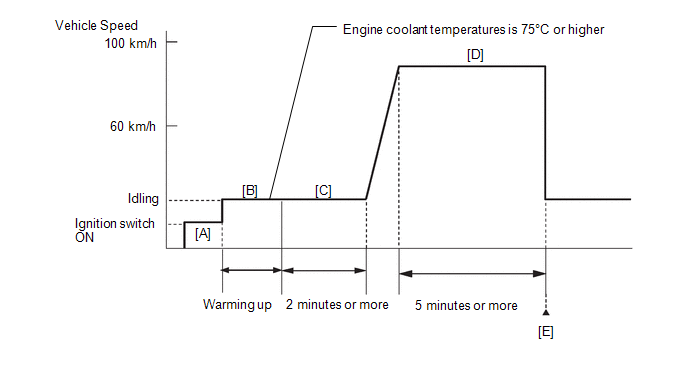
CONFIRMATION DRIVING PATTERN
- Connect the GTS to the DLC3.
- Turn the ignition switch to ON.
- Turn the GTS on.
- Clear the DTCs (even if no DTCs are stored, perform the clear DTC procedure).
- Turn the ignition switch off and wait for at least 30 seconds.
- Turn the ignition switch to ON [A].
- Turn the GTS on.
- Start the engine and warm it up until the engine coolant temperature is 75°C (167°F) or higher with all the accessories switched off [B].
- With the engine warmed up, idle the engine for 2 minutes or more [C].
-
Drive the vehicle at a speed between 60 and 100 km/h (37 and 62 mph) for 5 minutes or more [D].
CAUTION:
When performing the confirmation driving pattern, obey all speed limits and traffic laws.
- Enter the following menus: Powertrain / Engine / Trouble Codes [E].
-
Read the pending DTCs.
HINT:
If a pending DTC is output, the system is malfunctioning.
WIRING DIAGRAM
-
Refer to DTC P010012 for the mass air flow meter sub-assembly circuit.
Click here

-
Refer to DTC P003012 for the air fuel ratio sensor (sensor 1) circuit.
Click here

-
Refer to DTC P044313 for purge VSV circuit.
Click here

CAUTION / NOTICE / HINT
NOTICE:
Inspect the fuses for circuits related to this system before performing the following procedure.
HINT:
- A low air fuel ratio sensor (sensor 1) voltage could be caused by a rich air fuel mixture. Check for conditions that would cause the engine to run rich.
- A high air fuel ratio sensor (sensor 1) voltage could be caused by a lean air fuel mixture. Check for conditions that would cause the engine to run lean.
- Read Freeze Frame Data using the GTS. The ECM records vehicle and driving condition information as Freeze Frame Data the moment a DTC is stored. When troubleshooting, Freeze Frame Data can help determine if the vehicle was moving or stationary, if the engine was warmed up or not, if the air fuel ratio was lean or rich, and other data from the time the malfunction occurred.
- Sensor 1 refers to the sensor closest to the engine assembly.
- Sensor 2 refers to the sensor farthest away from the engine assembly.
PROCEDURE
| 1. | CHECK ANY OTHER DTCS OUTPUT (IN ADDITION TO DTC P017100, P017200, P117000 AND/OR P117B00) |
(a) Read the DTCs.
Powertrain > Engine > Trouble Codes| Result | Proceed to |
|---|---|
| P017100, P017200, P117000 and/or P117B00 is output | A |
| P017100, P017200, P117000 and/or P117B00 and other DTCs are output | B |
HINT:
If any DTCs other than P017100, P017200, P117000 and/or P117B00 are output, troubleshoot those DTCs first.
| B |
 | GO TO DTC CHART |
|

| 2. | PERFORM ACTIVE TEST USING GTS (CONTROL THE INJECTION MODE) |
(a) Start the engine and warm it up until the engine coolant temperature is 75°C (167°F) or higher with all the accessories switched off.
(b) Enter the following menus.
Powertrain > Engine > Active Test| Active Test Display |
|---|
| Control the Injection Mode |
| Data List Display |
|---|
| Injection Mode |
| Short FT B1S1 |
| Long FT B1S1 |
(c) According to the display on the GTS, read the Data List with the Active Test "Control the Injection Mode" set to Port.
OK:
| GTS Display | Specified Condition |
|---|---|
| Total of Short FT B1S1 and Long FT B1S1 | Between -20 and 20% |
(d) According to the display on the GTS, read the Data List with the Active Test "Control the Injection Mode" set to Direct.
OK:
| GTS Display | Specified Condition |
|---|---|
| Total of Short FT B1S1 and Long FT B1S1 | Between -20 and 20% |
| Item | Proceed to | |
|---|---|---|
| Port | Direct | |
| OK | OK | A |
| OK | NG | B |
| NG | OK | C |
| NG | NG | D |
| B |
 | GO TO STEP 4 |
| C |
 | GO TO STEP 11 |
| D |
 | GO TO STEP 12 |
|

| 3. | CHECK IF VEHICLE HAS RUN OUT OF FUEL IN PAST |
(a) Has the vehicle run out of fuel in the past?
| YES |
 | DTC CAUSED BY RUNNING OUT OF FUEL |
| NO |
 | CHECK FOR INTERMITTENT PROBLEMS |
| 4. | READ VALUE USING GTS (FUEL PRESSURE (HIGH)) |
(a) Enter the following menus.
Powertrain > Engine > Data List| Tester Display |
|---|
| Engine Speed |
| Fuel Pressure (High) |
| Injection Mode |
(b) Start the engine and warm it up until the engine coolant temperature is 75°C (167°F) or higher with all the accessories switched off.
(c) According to the display on the GTS, read the Data List.
Standard:
| GTS Display | Condition | Specified Condition |
|---|---|---|
| Fuel Pressure (High) |
| 2800 to 20000 kPag |
| NG |
 | GO TO STEP 7 |
|

| 5. | PERFORM ACTIVE TEST USING GTS (CONTROL THE INJECTION MODE (DIRECT)) |
(a) Start the engine and warm it up until the engine coolant temperature is 75°C (167°F) or higher.
(b) Enter the following menus.
Powertrain > Engine > Active Test| Active Test Display |
|---|
| Control the Injection Mode |
| Data List Display |
|---|
| High Pressure Fuel Pump Duty Ratio (D4) |
| Injection Mode |
| Short FT B1S1 |
| Long FT B1S1 |
(c) According to the display on the GTS, read the Data List with the Active Test "Control the Injection Mode" set to Direct.
| Item | Proceed to | ||
|---|---|---|---|
| Injection Mode | High Pressure Fuel Pump Duty Ratio (D4) | Total of Short FT B1S1 and Long FT B1S1 | |
| Direct | 10% to 40% | - | A |
| 40% or higher | -20% or less | B | |
| 10% or less | +20% or higher | ||
| 40% or higher | +20% or higher | C | |
| 10% or less | -20% or less | D | |
HINT:
Perform "Inspection After Repair" after replacing the fuel pressure sensor (for high pressure side).
Click here

| B |
 | REPLACE FUEL PRESSURE SENSOR (FOR HIGH PRESSURE SIDE) |
| C |
 | GO TO STEP 8 |
| D |
 | REPLACE ECM |
|

| 6. | PERFORM ACTIVE TEST USING GTS (CONTROL THE INJECTION MODE (DIRECT)) |
(a) Start the engine and warm it up until the engine coolant temperature is 75°C (167°F) or higher.
(b) Enter the following menus.
Powertrain > Engine > Active Test| Active Test Display |
|---|
| Control the Injection Mode |
| Data List Display |
|---|
| High Pressure Fuel Pump Duty Ratio (D4) |
| Injection Mode |
| Short FT B1S1 |
| Long FT B1S1 |
(c) According to the display on the GTS, read the Data List with the Active Test "Control the Injection Mode" set to Direct.
| Item | Proceed to | ||
|---|---|---|---|
| Injection Mode | High Pressure Fuel Pump Duty Ratio (D4) | Total of Short FT B1S1 and Long FT B1S1 | |
| Direct | 10 to 40% | -25% or less | A |
| 10 to 40% | +30% or higher | ||
| 10 to 40% | -25 to +25% | B | |
HINT:
Perform "Inspection After Repair" after replacing the direct fuel injector assembly.
Click here

| A |
 | REPLACE DIRECT FUEL INJECTOR ASSEMBLY (ALL CYLINDERS) |
| B |
 | CHECK FOR INTERMITTENT PROBLEMS |
| 7. | CHECK MISFIRE COUNT OF DIRECT INJECTION |
(a) Start the engine and warm it up until the engine coolant temperature is 75°C (167°F) or higher.
(b) Enter the following menus.
Powertrain > Engine > Active Test| Active Test Display |
|---|
| Control the Injection Mode |
| Data List Display |
|---|
| Injection Mode |
| Misfire Count Cylinder #1 |
| Misfire Count Cylinder #2 |
| Misfire Count Cylinder #3 |
(c) According to the display on the GTS, read the Data List with the Active Test "Control the Injection Mode" set to Direct.
| Injection Mode | Misfire Count | Proceed to |
|---|---|---|
| Direct | No misfire counts, or misfire counts occur randomly in all cylinders | A |
| Misfire counts occur in particular cylinder | B |
HINT:
Perform "Inspection After Repair" after replacing the direct fuel injector assembly.
Click here

| B |
 | REPLACE DIRECT FUEL INJECTOR ASSEMBLY |
|

| 8. | REPLACE FUEL PUMP ASSEMBLY (FOR HIGH PRESSURE SIDE) |
Click here

HINT:
Perform "Inspection After Repair" after replacing the fuel pump assembly (for high pressure side).
Click here

|

| 9. | CLEAR DTC |
(a) Clear the DTCs.
Powertrain > Engine > Clear DTCs(b) Turn the ignition switch off and wait for at least 30 seconds.
|

| 10. | CONFIRM WHETHER MALFUNCTION HAS BEEN SUCCESSFULLY REPAIRED |
(a) Drive the vehicle in accordance with the driving pattern described in Confirmation Driving Pattern.
(b) Read the DTCs.
Powertrain > Engine > Trouble Codes| Result | Proceed to |
|---|---|
| DTCs are not output | A |
| DTC P017100, P017200, P117000 and/or P117B00 is output | B |
| A |
 | END |
| B |
 | REPLACE ECM |
| 11. | INSPECT PORT FUEL INJECTOR ASSEMBLY |
(a) Check the injection volume (whether fuel volume is high or low, and whether injection pattern is poor).
Click here

HINT:
Perform "Inspection After Repair" after replacing the port fuel injector assembly.
Click here

| OK |
 | REPLACE ECM |
| NG |
 | REPLACE PORT FUEL INJECTOR ASSEMBLY |
| 12. | INSPECT PURGE VSV |
Click here

| NG |
 | REPLACE PURGE VSV |
|

| 13. | CHECK HARNESS AND CONNECTOR (PURGE VSV - ECM) |
(a) Disconnect the purge VSV connector.
(b) Disconnect the ECM connector.
(c) Measure the resistance according to the value(s) in the table below.
Standard Resistance:
| Tester Connection | Condition | Specified Condition |
|---|---|---|
| D104-45(PRG) - D96-2(EVP1) | Always | Below 1 Ω |
| D104-45(PRG) or D96-2(EVP1) - Body ground and other terminals | Always | 10 kΩ or higher |
| NG |
 | REPAIR OR REPLACE HARNESS OR CONNECTOR |
|

| 14. | CHECK PCV VALVE AND HOSE CONNECTIONS |
(a) Check the PCV hose connections.
(b) Check the PCV valve.
Click here

OK:
PCV hose and PCV valve are connected correctly and are not damaged.
| NG |
 | REPAIR OR REPLACE PCV VALVE OR HOSE |
|

| 15. | CHECK INTAKE SYSTEM |
(a) Check the intake system for vacuum leaks.
Click here

OK:
No leaks in intake system.
HINT:
Perform "Inspection After Repair" after repairing or replacing the intake system.
Click here

| NG |
 | REPAIR OR REPLACE INTAKE SYSTEM |
|

| 16. | PERFORM ACTIVE TEST USING GTS (CONTROL THE INJECTION VOLUME FOR A/F SENSOR) |
(a) Start the engine and warm it up until the engine coolant temperature reaches 75°C (167°F) or higher.
(b) Warm up the air fuel ratio sensors at an engine speed of 2500 rpm for 90 seconds.
(c) Enter the following menus.
Powertrain > Engine > Active Test| Active Test Display |
|---|
| Control the Injection Volume for A/F Sensor |
| Data List Display |
|---|
| A/F (O2) Sensor Current B1S1 |
| A/F (O2) Sensor Current B1S2 |
(d) Perform the Control the Injection Volume for A/F Sensor operation with the engine idling.
(e) Monitor the output values of the air fuel ratio sensor (sensor 1) and air fuel ratio sensor (sensor 2) (A/F (O2) Sensor Current B1S1 and A/F (O2) Sensor Current B1S2 displayed on the GTS.
HINT:
- The Control the Injection Volume for A/F Sensor operation lowers the fuel injection volume by 12.5% or increases the injection volume by 12.5%.
- The air fuel ratio sensor (sensor 1) has an output delay of a few seconds and the air fuel ratio sensor (sensor 2) has a maximum output delay of approximately 20 seconds.
- If the sensor output value does not change (almost no reaction) while performing the Active Test, the sensor may be malfunctioning.
Standard:
| GTS Display (Sensor) | Injection Volume | Status | Voltage |
|---|---|---|---|
| A/F (O2) Sensor Current B1S1 (Air fuel ratio [sensor 1]) | 12.5% | Rich | Below -0.075 mA |
| -12.5% | Lean | More than 0.037 mA | |
| A/F (O2) Sensor Current B1S2 (Air fuel ratio [sensor 2]) | 12.5% | Rich | Below -0.86 mA |
| -12.5% | Lean | More than 0.33 mA |
| Status of A/F (O2) Sensor Current B1S1 | Status of A/F (O2) Sensor Current B1S2 | Air Fuel Ratio Condition and Air Fuel Ratio Sensor Condition | Suspected Trouble Area | Proceed to |
|---|---|---|---|---|
| Lean/Rich | Lean/Rich | Normal | - | A |
| Lean | Lean | Actual air fuel ratio lean |
| |
| Rich | Rich | Actual air fuel ratio rich |
| |
| Lean | Lean/Rich | Air fuel ratio sensor (sensor 1) malfunction |
| B |
| Rich | Lean/Rich | Air fuel ratio sensor (sensor 1) malfunction |
|
- Lean: During the Control the Injection Volume for A/F Sensor Active Test, the air fuel ratio sensor (sensor 1) output current (A/F (O2) Sensor Current B1S1) is consistently more than 0.037 mA, and the air fuel ratio sensor (sensor 2) output current (A/F (O2) Sensor Current B1S2) is consistently more than 0.33 mA.
- Rich: During the Control the Injection Volume for A/F Sensor Active Test, the air fuel ratio sensor (sensor 1) output current (A/F (O2) Sensor Current B1S1) is consistently below -0.075 mA, and the air fuel ratio sensor (sensor 2) output current (A/F (O2) Sensor Current B1S2) is consistently below -0.86 mA.
- Lean/Rich: During the Control the Injection Volume for A/F Sensor Active Test, the output current of the air fuel ratio sensor (sensor 1) or air fuel ratio sensor (sensor 2) alternate correctly.
HINT:
Refer to "Data List / Active Test" [A/F (O2) Sensor Current B1S1 and A/F (O2) Sensor Current B2S1].
Click here

| B |
 | GO TO STEP 24 |
|

| 17. | READ VALUE USING GTS (COOLANT TEMPERATURE) |
(a) Enter the following menus.
Powertrain > Engine > Data List| Tester Display |
|---|
| Coolant Temperature |
(b) Read the Data List twice, when the engine is both cold and warmed up.
Standard:
| GTS Display | Condition | Specified Condition |
|---|---|---|
| Coolant Temperature | Cold engine | Same as ambient air temperature |
| After fully warming up | Between 75 and 105°C (167 and 221°F) |
HINT:
- The engine can be judged as fully warmed up after warming up the engine with the air conditioning off until the electric cooling fan starts to operate.
- Leaving the vehicle overnight allows the engine temperature to be the same as the ambient temperature.
| NG |
 | REPLACE ENGINE COOLANT TEMPERATURE SENSOR |
|

| 18. | INSPECT MASS AIR FLOW METER SUB-ASSEMBLY |
Click here

| NG |
 | GO TO STEP 30 |
|

| 19. | CHECK FUEL PRESSURE (FOR LOW PRESSURE SIDE) |
(a) Check the fuel pressure (for low pressure side).
Click here

| NG |
 | GO TO STEP 23 |
|

| 20. | CHECK FOR EXHAUST GAS LEAK |
(a) Check for exhaust gas leaks.
OK:
No gas leaks.
HINT:
Perform "Inspection After Repair" after repairing or replacing the exhaust system.
Click here

| NG |
 | REPAIR OR REPLACE EXHAUST SYSTEM |
|

| 21. | INSPECT SPARK PLUG |
Click here

HINT:
Perform "Inspection After Repair" after replacing the spark plug.
Click here

| NG |
 | REPLACE SPARK PLUG |
|

| 22. | CHECK FOR SPARK (SPARK TEST) |
(a) Perform a spark test.
Click here

HINT:
- If the result of the spark test is normal, proceed to the next step.
-
Perform "Inspection After Repair" after replacing the spark plug or ignition coil assembly.
Click here

| NEXT |
 | GO TO STEP 30 |
| 23. | CHECK FUEL LINE |
(a) Check the fuel lines for leaks or blockage.
| OK |
 | GO TO FUEL PUMP CONTROL CIRCUIT |
| NG |
 | REPAIR OR REPLACE FUEL SYSTEM |
| 24. | INSPECT AIR FUEL RATIO SENSOR (SENSOR 1) (HEATER RESISTANCE) |
Click here

HINT:
Perform "Inspection After Repair" after replacing the air fuel ratio sensor (sensor 1).
Click here

| NG |
 | REPLACE AIR FUEL RATIO SENSOR (SENSOR 1) |
|

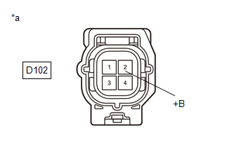
| 25. | CHECK TERMINAL VOLTAGE (POWER SOURCE OF AIR FUEL RATIO SENSOR (SENSOR 1)) |
(a) Disconnect the air fuel ratio sensor (sensor 1) connector.
(b) Turn the ignition switch to ON.
| (c) Measure the voltage according to the value(s) in the table below. Standard Voltage:
|
|
| NG |
 | REPAIR OR REPLACE AIR FUEL RATIO SENSOR (SENSOR 1) POWER SOURCE CIRCUIT |
|

| 26. | CHECK HARNESS AND CONNECTOR (AIR FUEL RATIO SENSOR (SENSOR 1) - ECM) |
(a) Disconnect the air fuel ratio sensor (sensor 1) connector.
(b) Disconnect the ECM connector.
(c) Measure the resistance according to the value(s) in the table below.
Standard Resistance:
| Tester Connection | Condition | Specified Condition |
|---|---|---|
| D102-1(HA1A) - D104-2(HA1A) | Always | Below 1 Ω |
| D102-3(A1A+) - D104-95(A1A+) | Always | Below 1 Ω |
| D102-4(A1A-) - D102-94(A1A-) | Always | Below 1 Ω |
| D102-1(HA1A) or D104-2(HA1A) - Body ground and other terminals | Always | 10 kΩ or higher |
| D102-3(A1A+) or D104-95(A1A+) - Body ground and other terminals | Always | 10 kΩ or higher |
| D102-4(A1A-) or D102-94(A1A-) - Body ground and other terminals | Always | 10 kΩ or higher |
| NG |
 | REPAIR OR REPLACE HARNESS OR CONNECTOR |
|

| 27. | REPLACE AIR FUEL RATIO SENSOR (SENSOR 1) |
Click here

HINT:
Perform "Inspection After Repair" after replacing the air fuel ratio sensor (sensor 1).
Click here

|

| 28. | CLEAR DTC |
(a) Clear the DTCs.
Powertrain > Engine > Clear DTCs(b) Turn the ignition switch off and wait for at least 30 seconds.
|

| 29. | CONFIRM WHETHER MALFUNCTION HAS BEEN SUCCESSFULLY REPAIRED |
(a) Drive the vehicle in accordance with the driving pattern described in Confirmation Driving Pattern.
(b) Read the DTCs.
Powertrain > Engine > Trouble Codes| Result | Proceed to |
|---|---|
| DTCs are not output | A |
| P017100, P017200, P117000 and/or P117B00 is output | B |
| A |
 | END |
|

| 30. | CHECK HARNESS AND CONNECTOR (MASS AIR FLOW METER SUB-ASSEMBLY CONNECTOR CONNECTION) |
(a) Check the connection and terminal contact pressure of connectors and wire harnesses between the mass air flow meter sub-assembly and ECM.
Click here

HINT:
Repair any problems.
|

| 31. | CLEAR DTC |
(a) Clear the DTCs.
Powertrain > Engine > Clear DTCs(b) Turn the ignition switch off and wait for at least 30 seconds.
|

| 32. | CHECK WHETHER DTC OUTPUT RECURS (DTC P017100, P017200, P117000 AND/OR P117B00) |
(a) Drive the vehicle in accordance with the driving pattern described in Confirmation Driving Pattern.
(b) Read the DTCs.
Powertrain > Engine > Trouble Codes| Result | Proceed to |
|---|---|
| DTCs are not output | A |
| P017100, P017200, P117000 and/or P117B00 is output | B |
| A |
 | END |
|

| 33. | CHECK HARNESS AND CONNECTOR (MASS AIR FLOW METER SUB-ASSEMBLY - ECM) |
(a) Disconnect the mass air flow meter sub-assembly connector.
(b) Disconnect the ECM connector.
(c) Measure the resistance according to the value(s) in the table below.
Standard Resistance:
| Tester Connection | Condition | Specified Condition |
|---|---|---|
| D23-3(VCC) - D104-84(VCVG) | Always | Below 1 Ω |
| D23-1(FG) - D104-107(VG) | Always | Below 1 Ω |
| D23-2(E2G) - D104-83(E2G) | Always | Below 1 Ω |
| D23-3(VCC) or D104-84(VCVG) - Body ground and other terminals | Always | 10 kΩ or higher |
| D23-1(FG) or D104-107(VG) - Body ground and other terminals | Always | 10 kΩ or higher |
| NG |
 | REPAIR OR REPLACE HARNESS OR CONNECTOR |
|

| 34. | REPLACE MASS AIR FLOW METER SUB-ASSEMBLY |
Click here

HINT:
- If the result of the inspection performed in steps 18 and 30 (READ VALUE USING GTS (MASS AIR FLOW SENSOR)) indicate no problem, proceed to the next step without replacing the mass air flow meter sub-assembly.
-
Perform "Inspection After Repair" after replacing the mass air flow meter sub-assembly.
Click here

|

| 35. | CLEAR DTC |
(a) Clear the DTCs.
Powertrain > Engine > Clear DTCs(b) Turn the ignition switch off and wait for at least 30 seconds.
|

| 36. | CONFIRM WHETHER MALFUNCTION HAS BEEN SUCCESSFULLY REPAIRED |
(a) Drive the vehicle in accordance with the driving pattern described in Confirmation Driving Pattern.
(b) Read the DTCs.
Powertrain > Engine > Trouble Codes| Result | Proceed to |
|---|---|
| DTCs are not output | A |
| P017100, P017200, P117000 and/or P117B00 is output | B |
| A |
 | END |
| B |
 | REPLACE ECM |
 A/F (O2) Sensor Circuit Bank 1 Sensor 2 Circuit Current (Voltage) Below Threshold (P013616)
DESCRIPTION Refer to DTC P003612. Click here
DTC No. Detection Item DTC Detection Condition Trouble Area MIL Note P013616 A/F (O2) Sensor Circuit Bank 1 Sensor 2 Circuit Current (Voltage) Below Threshold Either of the following conditions is met (2 trip detection logic)...
 Fuel Rail Pressure Sensor "A" Circuit Short to Ground (P019011)
DESCRIPTION
The fuel pressure sensor (for high pressure side) is installed on the fuel delivery pipe (for high pressure side). The fuel pressure sensor (for high pressure side) changes the fuel pressure for high pressure side into an electrical signal and sends the signal to the ECM...
Other information:
Toyota Yaris XP210 (2020-2026) Reapir and Service Manual: Diagnosis System
DIAGNOSIS SYSTEM DESCRIPTION (a) Power window control system data and Diagnostic Trouble Codes (DTCs) can be read through the vehicle Data Link Connector 3 (DLC3). When the system seems to be malfunctioning, use the GTS to check for malfunctions and perform repairs...
Toyota Yaris XP210 (2020-2026) Reapir and Service Manual: Disposal
DISPOSAL PROCEDURE 1. DISPOSE OF REAR SHOCK ABSORBER ASSEMBLY (a) Extend the piston rod and secure the rear shock absorber assembly at an angle in a vise. (b) Using a hacksaw, slowly make a hole at the position indicated by the arrow in the illustration to discharge the gas inside...
Categories
- Manuals Home
- Toyota Yaris Owners Manual
- Toyota Yaris Service Manual
- Adjustment
- G16e-gts (engine Mechanical)
- Removal
- New on site
- Most important about car
Key Suspend Function
If a key is left in the vehicle, the functions of the key left in the vehicle are temporarily suspended to prevent theft of the vehicle.
To restore the functions, press the unlock button on the functions-suspended key in the vehicle.