Toyota Yaris: Sfi System / Fuel Rail Pressure Sensor "A" Circuit Short to Ground (P019011)
DESCRIPTION
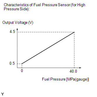
The fuel pressure sensor (for high pressure side) is installed on the fuel delivery pipe (for high pressure side). The fuel pressure sensor (for high pressure side) changes the fuel pressure for high pressure side into an electrical signal and sends the signal to the ECM. Then the ECM controls the pump discharge using this feedback to maintain the fuel's target pressure between 2.4 and 20 MPa (24.4 and 204 kgf/cm2, 348 and 2900 psi).
| DTC No. | Detection Item | DTC Detection Condition | Trouble Area | MIL | Note |
|---|---|---|---|---|---|
| P019011 | Fuel Rail Pressure Sensor "A" Circuit Short to Ground | The fuel pressure sensor (for high pressure side) output voltage is less than 0.293 V for 3 seconds or more (1 trip detection logic). |
| Comes on | SAE: P0192 |
HINT:
When a DTC is output, check the Data List item "Fuel Pressure (High)" using the GTS.
Click here

| DTC No. | Fuel Pressure (High) | Malfunction |
|---|---|---|
| P019011 | Approximately 0 kPag |
|
If the Data List displays a normal value, the normal value may be due to a temporary recovery from the malfunction condition. Check for intermittent problems.
MONITOR DESCRIPTION
This DTC is stored if the fuel pressure sensor (for high pressure side) output voltage is out of the standard range due to an open or short in the sensor circuit.
Example:
If the fuel pressure sensor (for high pressure side) output voltage is less than 0.293 V for 3 seconds or more, the ECM will illuminate the MIL and store this DTC.
MONITOR STRATEGY
| Required Sensors/Components | Fuel pressure sensor (for high pressure side) |
| Frequency of Operation | Continuous |
CONFIRMATION DRIVING PATTERN
- Connect the GTS to the DLC3.
- Turn the ignition switch to ON.
- Turn the GTS on.
- Clear the DTCs (even if no DTCs are stored, perform the clear DTC procedure).
- Turn the ignition switch off and wait for at least 30 seconds.
- Start the engine [A].
- Idle the engine for 10 seconds [B].
- Turn the GTS on.
- Enter the following menus: Powertrain / Engine / Trouble Codes [C].
-
Read the pending DTCs.
HINT:
- If a pending DTC is output, the system is malfunctioning.
- If a pending DTC is not output, perform the following procedure.
- Enter the following menus: Powertrain / Engine / Utility / All Readiness.
- Input the DTC: P019011.
-
Check the DTC judgment result.
GTS Display
Description
NORMAL
- DTC judgment completed
- System normal
ABNORMAL
- DTC judgment completed
- System abnormal
INCOMPLETE
- DTC judgment not completed
- Perform driving pattern after confirming DTC enabling conditions
HINT:
- If the judgment result is NORMAL, the system is normal.
- If the judgment result is ABNORMAL, the system has a malfunction.
- If the judgment result is INCOMPLETE, perform steps [B] through [C] again.
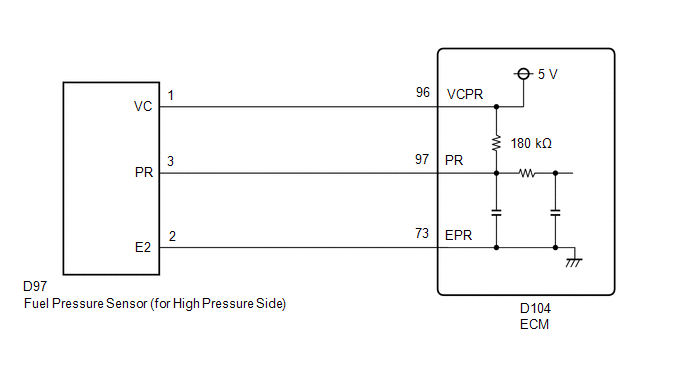
WIRING DIAGRAM
CAUTION / NOTICE / HINT
HINT:
Read Freeze Frame Data using the GTS. The ECM records vehicle and driving condition information as Freeze Frame Data the moment a DTC is stored. When troubleshooting, Freeze Frame Data can help determine if the vehicle was moving or stationary, if the engine was warmed up or not, if the air fuel ratio was lean or rich, and other data from the time the malfunction occurred.
PROCEDURE
| 1. | CHECK HARNESS AND CONNECTOR |
HINT:
Make sure that the connector is properly connected. If it is not, securely connect it and check for DTCs again.
(a) Disconnect the fuel pressure sensor (for high pressure side) connector.
(b) Turn the ignition switch to ON.
| (c) Measure the voltage according to the value(s) in the table below. Standard Voltage:
|
|
(d) Turn the ignition switch off and wait for at least 30 seconds.
(e) Measure the resistance according to the value(s) in the table below.
Standard Resistance:
| Tester Connection | Condition | Specified Condition |
|---|---|---|
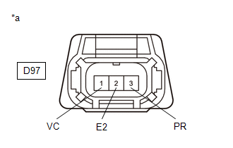
| D97-1(VC) - D97-3(PR) | Ignition switch off | 171 to 189 kΩ |
HINT:
Perform "Inspection After Repair" after replacing the fuel pressure sensor (for high pressure side).
Click here

| OK |
 | REPLACE FUEL PRESSURE SENSOR (FOR HIGH PRESSURE SIDE) |
|

| 2. | CHECK HARNESS AND CONNECTOR (FUEL PRESSURE SENSOR (FOR HIGH PRESSURE SIDE) - ECM) |
(a) Disconnect the fuel pressure sensor (for high pressure side) connector.
(b) Disconnect the ECM connector.
(c) Measure the resistance according to the value(s) in the table below.
Standard Resistance:
| Tester Connection | Condition | Specified Condition |
|---|---|---|
| D97-1(VC) - D104-96(VCPR) | Always | Below 1 Ω |
| D97-3(PR) or D104-97(PR) - Body ground and other terminals | Always | 10 kΩ or higher |
| OK |
 | REPLACE ECM |
| NG |
 | REPAIR OR REPLACE HARNESS OR CONNECTOR |
 System Too Lean Bank 1 (P017100,P017200,P117000,P117B00)
DESCRIPTION The fuel trim is related to the feedback compensation value, not to the basic injection duration. The fuel trim consists of both the short-term and long-term fuel trims...
 Engine Oil Temperature Sensor Circuit Short to Ground (P019511)
DESCRIPTION
The engine oil temperature sensor (engine oil pressure and temperature sensor) replaces the oil temperature with electrical signals and outputs them to the ECM...
Other information:
Toyota Yaris XP210 (2020-2026) Reapir and Service Manual: Front Left Air Mix Damper Control Servo Motor Actuator Stuck Off (B144C7F)
DESCRIPTION The No. 1 air conditioning radiator damper servo sub-assembly sends pulse signals to inform the air conditioning amplifier assembly of the damper position. The air conditioning amplifier assembly activates the motor (normal or reverse) based on these signals to move the air outlet damper to the appropriate position, which controls the air outlet switching...
Toyota Yaris XP210 (2020-2026) Reapir and Service Manual: Removal
REMOVAL CAUTION / NOTICE / HINT HINT: Use the same procedure for the RH side and LH side. The following procedure is for the LH side. PROCEDURE 1. REMOVE ROOF DRIP SIDE MOULDING (a) Apply protective tape around the roof drip side moulding. (b) for 1-clip Type: (1) Disengage the clip...
Categories
- Manuals Home
- Toyota Yaris Owners Manual
- Toyota Yaris Service Manual
- Adjustment
- Removal
- Fuel Gauge
- New on site
- Most important about car
Fuel-Filler Lid and Cap
WARNING
When removing the fuel-filler cap, loosen the cap slightly and wait for any hissing to stop, then remove it
Fuel spray is dangerous. Fuel can burn skin and eyes and cause illness if ingested. Fuel spray is released when there is pressure in the fuel tank and the fuel-filler cap is removed too quickly.