Toyota Yaris: Sfi System / Engine Oil Temperature Sensor Circuit Short to Ground (P019511)
DESCRIPTION
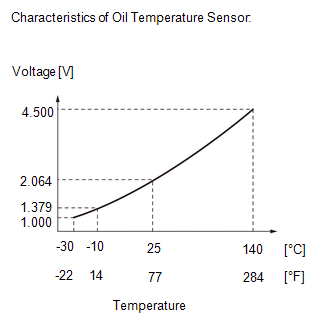
The engine oil temperature sensor (engine oil pressure and temperature sensor) replaces the oil temperature with electrical signals and outputs them to the ECM.
| DTC No. | Detection Item | DTC Detection Condition | Trouble Area | MIL | Note |
|---|---|---|---|---|---|
| P019511 | Engine Oil Temperature Sensor Circuit Short to Ground | The engine oil temperature sensor (engine oil pressure and temperature sensor) output voltage is below 0.535 V for 5 seconds or more (1 trip detection logic). |
| - | SAE: P0197 |
HINT:
When a DTC is output, check the Data List item "Engine Oil Temperature Sensor" using the GTS.
Click here

| DTC No. | Engine Oil Temperature Sensor | Malfunction |
|---|---|---|
| P019511 | -40°C (-40°F) |
|
If the Data List displays a normal value, the normal value may be due to a temporary recovery from the malfunction condition. Check for intermittent problems.
MONITOR DESCRIPTION
The ECM monitors the engine oil temperature sensor (engine oil pressure and temperature sensor) and uses the sensor voltage to calculate the engine oil temperature. If the engine oil temperature sensor (engine oil pressure and temperature sensor) output voltage deviates from the normal operating range, the ECM determines that the engine oil temperature sensor (engine oil pressure and temperature sensor) circuit is malfunctioning and stores this DTC.
Example:
If the engine oil temperature sensor (engine oil pressure and temperature sensor) output voltage is below 0.535 V for 5 seconds or more, the ECM will store this DTC.
MONITOR STRATEGY
| Frequency of Operation | Continuous |
CONFIRMATION DRIVING PATTERN
- Connect the GTS to the DLC3.
- Turn the ignition switch to ON.
- Turn the GTS on.
- Clear the DTCs (even if no DTCs are stored, perform the clear DTC procedure).
- Turn the ignition switch off and wait for at least 30 seconds.
- Turn the ignition switch to ON.
- Turn the GTS on.
- Wait 10 seconds or more.
- Enter the following menus: Powertrain / Engine / Trouble Codes.
-
Read the pending DTCs.
HINT:
- If a pending DTC is output, the system is malfunctioning.
- If a pending DTC is not output, perform the following procedure.
- Enter the following menus: Powertrain / Engine / Utility / All Readiness.
- Input the DTC: P019511.
-
Check the DTC judgment result.
GTS Display
Description
NORMAL
- DTC judgment completed
- System normal
ABNORMAL
- DTC judgment completed
- System abnormal
INCOMPLETE
- DTC judgment not completed
- Perform driving pattern after confirming DTC enabling conditions
HINT:
- If the judgment result is NORMAL, the system is normal.
- If the judgment result is ABNORMAL, the system has a malfunction.
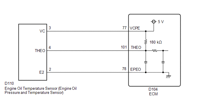
WIRING DIAGRAM
Production date from 2021/04 to 2021/07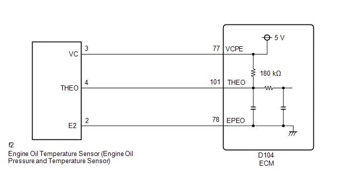 Production date from 2021/07
CAUTION / NOTICE / HINT
HINT:
Read Freeze Frame Data using the GTS. The ECM records vehicle and driving condition information as Freeze Frame Data the moment a DTC is stored. When troubleshooting, Freeze Frame Data can help determine if the vehicle was moving or stationary, if the engine was warmed up or not, if the air fuel ratio was lean or rich, and other data from the time the malfunction occurred.
PROCEDURE
| 1. | CHECK VEHICLE SPECIFICATION |
(a) Check the vehicle specification
| Result | Proceed to |
|---|---|
| Production date from 2021/04 to 2021/07 | A |
| Production date from 2021/07 | B |
| B |
 | GO TO STEP 4 |
|

| 2. | CHECK HARNESS AND CONNECTOR |
HINT:
Make sure that the connector is properly connected. If it is not, securely connect it and check for DTCs again.
(a) Disconnect the engine oil temperature sensor (engine oil pressure and temperature sensor) connector.
(b) Turn the ignition switch to ON.
| (c) Measure the voltage according to the value(s) in the table below. Standard Voltage:
|
|
(d) Turn the ignition switch off and wait for at least 30 seconds.
(e) Measure the resistance according to the value(s) in the table below.
Standard Resistance:
| Tester Connection | Switch Condition | Specified Condition |
|---|---|---|
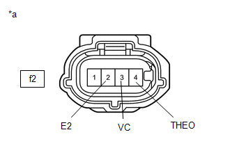
| f2-3(VC) - f2-4(THEO) | Ignition switch off | 171 to 189 kΩ |
| OK |
 | REPLACE ENGINE OIL TEMPERATURE SENSOR (ENGINE OIL PRESSURE AND TEMPERATURE SENSOR) |
|

| 3. | CHECK HARNESS AND CONNECTOR (ENGINE OIL TEMPERATURE SENSOR (ENGINE OIL PRESSURE AND TEMPERATURE SENSOR) - ECM) |
(a) Disconnect the engine oil temperature sensor (engine oil pressure and temperature sensor) connector.
(b) Disconnect the ECM connector.
(c) Measure the resistance according to the value(s) in the table below.
Standard Resistance:
| Tester Connection | Condition | Specified Condition |
|---|---|---|
| f2-3(VC) - D104-77(VCPE) | Always | Below 1 Ω |
| f2-4(THEO) or D104-101(THEO) - Body ground and other terminals | Always | 10 kΩ or higher |
| OK |
 | REPLACE ECM |
| NG |
 | REPAIR OR REPLACE HARNESS OR CONNECTOR |
| 4. | CHECK HARNESS AND CONNECTOR |
HINT:
Make sure that the connector is properly connected. If it is not, securely connect it and check for DTCs again.
(a) Disconnect the engine oil temperature sensor (engine oil pressure and temperature sensor) connector.
(b) Turn the ignition switch to ON.
| (c) Measure the voltage according to the value(s) in the table below. Standard Voltage:
|
|
(d) Turn the ignition switch off and wait for at least 30 seconds.
(e) Measure the resistance according to the value(s) in the table below.
Standard Resistance:
| Tester Connection | Switch Condition | Specified Condition |
|---|---|---|
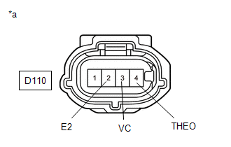
| D110-3(VC) - D110-4(THEO) | Ignition switch off | 171 to 189 kΩ |
| OK |
 | REPLACE ENGINE OIL TEMPERATURE SENSOR (ENGINE OIL PRESSURE AND TEMPERATURE SENSOR) |
|

| 5. | CHECK HARNESS AND CONNECTOR (ENGINE OIL TEMPERATURE SENSOR (ENGINE OIL PRESSURE AND TEMPERATURE SENSOR) - ECM) |
(a) Disconnect the engine oil temperature sensor (engine oil pressure and temperature sensor) connector.
(b) Disconnect the ECM connector.
(c) Measure the resistance according to the value(s) in the table below.
Standard Resistance:
| Tester Connection | Condition | Specified Condition |
|---|---|---|
| D110-3(VC) - D104-77(VCPE) | Always | Below 1 Ω |
| D110-4(THEO) or D104-101(THEO) - Body ground and other terminals | Always | 10 kΩ or higher |
| OK |
 | REPLACE ECM |
| NG |
 | REPAIR OR REPLACE HARNESS OR CONNECTOR |
 Fuel Rail Pressure Sensor "A" Circuit Short to Ground (P019011)
DESCRIPTION
The fuel pressure sensor (for high pressure side) is installed on the fuel delivery pipe (for high pressure side). The fuel pressure sensor (for high pressure side) changes the fuel pressure for high pressure side into an electrical signal and sends the signal to the ECM...
 Cylinder 1 Injector "A" Circuit Open (P020113-P020313,P062D13)
DESCRIPTION The D-4S system has two fuel injection systems. One is an in-cylinder direct injection system that directly injects pressurized fuel into the combustion chamber...
Other information:
Toyota Yaris XP210 (2020-2026) Reapir and Service Manual: Installation
INSTALLATION PROCEDURE 1. INSTALL NO. 8 ANTENNA CORD SUB-ASSEMBLY (a) Engage the guide to install the No. 8 antenna cord sub-assembly. (b) Install the bolt. Torque: 10 N·m {102 kgf·cm, 7 ft·lbf} (c) Connect the connector. 2. INSTALL NO...
Toyota Yaris XP210 (2020-2026) Reapir and Service Manual: Replacement
REPLACEMENT PROCEDURE 1. SEPARATE NO. 1 ENGINE UNDER COVER ASSEMBLY Click here 2. DRAIN ENGINE COOLANT CAUTION: When engine coolant is hot, do not remove the reserve tank cap or the radiator drain cock plug. Fluid and steam may spray out due to high pressure, possibly resulting in burns...
Categories
- Manuals Home
- Toyota Yaris Owners Manual
- Toyota Yaris Service Manual
- Immobilizer System
- Battery Monitor Module General Electrical Failure (P058A01)
- Removal
- New on site
- Most important about car
Fuel Gauge
The fuel gauge shows approximately how much fuel is remaining in the tank when the ignition is switched ON. We recommend keeping the tank over 1/4 full.
