Toyota Yaris: Wiper And Washer System / Terminals Of Ecu
TERMINALS OF ECU
CHECK MAIN BODY ECU (MULTIPLEX NETWORK BODY ECU) AND POWER DISTRIBUTION BOX ASSEMBLY
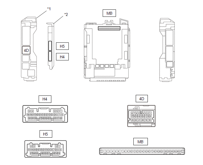
| *1 | Power Distribution Box Assembly | *2 | Main Body ECU (Multiplex Network Body ECU) |
(a) Remove the main body ECU (multiplex network body ECU) from the power distribution box assembly.
(b) Measure the voltage and resistance according to the value(s) in the table below.
| Terminal No. (Symbol) | Terminal Description | Condition | Specified Condition |
|---|---|---|---|
| MB-26 (BCEU) - Body ground | Auxiliary battery power supply | Ignition switch off | 11 to 14 V |
| MB-27 (IGR) - Body ground | IG power source | Ignition switch off | Below 1 V |
| Ignition switch ON | 11 to 14 V | ||
| MB-13 (GND1) - Body ground | Ground | Always | Below 1 Ω |
(c) Install the main body ECU (multiplex network body ECU) to power distribution box assembly.
(d) Measure the voltage and check for pulses according to the value(s) in the table below.
| Terminal No. (Symbol) | Terminal Description | Condition | Specified Condition |
|---|---|---|---|
| 4D-5 - Body ground | CXPI communication line | Ignition switch ON | Pulse generation |
| H4-6 (WPS) - Body ground | Wiper Relay operation signal | Less than approximately 60 seconds after ignition switch turned off | 11 to 14 V |
| Approximately 60 seconds or more after ignition switch turned off | Below 1 V | ||
| H5-11 (LIN4) - Body ground | LIN communication line | Ignition switch ON | Pulse generation |
CHECK WINDSHIELD WIPER RELAY ASSEMBLY

(a) Disconnect the A50 and A49 windshield wiper relay assembly connectors.
(b) Measure the voltage and resistance according to the value(s) in the table below.
| Terminal No. (Symbol) | Terminal Description | Condition | Specified Condition |
|---|---|---|---|
| A50-3 (E) - Body ground | Ground | Always | Below 1 Ω |
| A50-5 (EWS) - Body ground | Ground | Always | Below 1 Ω |
| A50-6 (IGWS) - Body ground | Washer circuit IG power source | Ignition switch off | Below 1 V |
| Ignition switch ON | 11 to 14 V | ||
| A50-8 (+B) - Body ground | Ignition switch ON signal (Power source circuit) | Ignition switch ON | 11 to 14 V |
| Less than approximately 60 seconds after ignition switch turned off | |||
| Approximately 60 seconds or more after ignition switch turned off | Below 1 V | ||
| A49-5 (ES) - Body ground | Ground | Always | Below 1 Ω |
(c) Connect the A50 and A49 windshield wiper relay assembly connectors.
(d) Measure the voltage and resistance and check for pulses according to the value(s) in the table below.
| Terminal No. (Symbol) | Terminal Description | Condition | Specified Condition |
|---|---|---|---|
| A50-1 (+WR) - Body ground | Front washer operation signal | Ignition switch ON, front washer operating | 11 to 14 V |
| A50-2 (+1) - Body ground | LO operation signal to windshield wiper motor assembly | Ignition switch ON, windshield wiper motor assembly operating in LO | 11 to 14 V |
| A50-4 (+2) - Body ground | HI operation signal to windshield wiper motor assembly | Ignition switch ON, windshield wiper motor assembly operating in HI | 11 to 14 V |
| A49-3 (2S) - Body ground | Windshield wiper motor assembly HI operation signal | Windshield wiper motor assembly stopped | 4.5 to 5.5 V |
| Windshield wiper motor assembly operating in HI | Below 1 V | ||
| A49-4 (MPX1) - Body ground | CXPI communication line | Ignition switch ON | Pulse generation |
| Less than approximately 100 seconds after ignition switch turned off | |||
| Approximately 100 seconds or more after ignition switch turned off | 11 to 14 V | ||
| A49-6 (+SM) - Body ground | Windshield wiper motor assembly position detection signal | Windshield wiper motor assembly in LO or HI operation | Below 1 V ←→ 11 to 14V |
| Windshield wiper motor assembly stopped | Below 1 V |
CHECK RAIN SENSOR

(a) Disconnect the V9 rain sensor connector.
(b) Measure the voltage and resistance and check for pulses according to the value(s) in the table below.
| Terminal No. (Symbol) | Terminal Description | Condition | Specified Condition |
|---|---|---|---|
| V9-2 (ES) - Body ground | Ground | Always | Below 1 Ω |
| V9-3 (MPX) - Body ground | LIN communication signal | Ignition switch ON | Pulse generation |
| V9-4 (SIG) - Body ground | IG power source circuit | Ignition switch off | Below 1 V |
| Ignition switch ON | 11 to 14 V |
 Problem Symptoms Table
PROBLEM SYMPTOMS TABLE NOTICE: If the main body ECU (multiplex network body ECU) is replaced, refer to the Registration. Click here
HINT:
Use the table below to help determine the cause of problem symptoms...

Other information:
Toyota Yaris XP210 (2020-2026) Reapir and Service Manual: Wiper Module Missing Message (B235787)
DESCRIPTION The main body ECU (multiplex network body ECU) and windshield wiper relay assembly communicate via CXPI communication. The main body ECU (multiplex network body ECU) stores this DTC if communication becomes abnormal. DTC No. Detection Item DTC Detection Condition Trouble Area Memory DTC Output from B235787 Wiper Module Missing Message Auxiliary battery voltage is 9...
Toyota Yaris XP210 (2020-2026) Reapir and Service Manual: Camshaft Position Sensor "A" Bank 1 or Single Sensor Circuit Short to Ground (P034011,P034015)
DESCRIPTION The camshaft position sensor (for intake camshaft) (VV1 signal) consists of a magnet and MRE (Magneto-Resistive Element). The intake camshaft has a timing rotor for the camshaft position sensor. When the intake camshaft rotates, changes occur in the air gaps between the timing rotor and MRE, which affects the magnetic field...
Categories
- Manuals Home
- Toyota Yaris Owners Manual
- Toyota Yaris Service Manual
- Immobilizer System
- Diagnostic Trouble Code Chart
- Engine Start Function When Key Battery is Dead
- New on site
- Most important about car
Refueling
Before refueling, close all the doors, windows, and the liftgate/trunk lid, and switch the ignition OFF.
To open the fuel-filler lid, pull the remote fuel-filler lid release.
