Toyota Yaris: Sfi System / Camshaft Position Sensor "A" Bank 1 or Single Sensor Circuit Short to Ground (P034011,P034015)
DESCRIPTION
The camshaft position sensor (for intake camshaft) (VV1 signal) consists of a magnet and MRE (Magneto-Resistive Element).
The intake camshaft has a timing rotor for the camshaft position sensor. When the intake camshaft rotates, changes occur in the air gaps between the timing rotor and MRE, which affects the magnetic field. As a result, the resistance of the MRE material fluctuates. The camshaft position sensor converts the camshaft rotation data to pulse signals, uses the pulse signals. The ECM uses the pulse signals to determine the camshaft angle. Then the ECM uses this data to control fuel injection duration and injection timing.
| DTC No. | Detection Item | DTC Detection Condition | Trouble Area | MIL | Note |
|---|---|---|---|---|---|
| P034011 | Camshaft Position Sensor "A" Bank 1 or Single Sensor Circuit Short to Ground | The camshaft position sensor (for intake camshaft) output voltage is less than 0.3 V for 4 seconds or more (1 trip detection logic). |
| Comes on | SAE: P0342 |
| P034015 | Camshaft Position Sensor "A" Bank 1 or Single Sensor Circuit Short to Battery or Open | The camshaft position sensor (for intake camshaft) output voltage is higher than 4.7 V for 4 seconds or more (1 trip detection logic). |
| Comes on | SAE: P0343 |
-
Reference: Inspection using an oscilloscope.
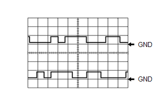
HINT:
- The correct waveform is as shown.
- VV1 stands for the camshaft position sensor signal (for intake camshaft), and EV1 stands for the camshaft position sensor signal (for exhaust camshaft).
ECM Terminal Name
CH1: Between VV1+ and VV1-
CH2: Between EV1+ and EV1-
Tester Range
5 V/DIV., 20 ms./DIV.
Condition
Idling with warm engine
MONITOR DESCRIPTION
If the output voltage transmitted by the camshaft position sensor (for intake camshaft) remains low or high, the ECM interprets this as a malfunction in the sensor circuit, illuminates the MIL and stores a DTC.
MONITOR STRATEGY
| Required Sensors/Components (Main) | Camshaft position sensor (for intake camshaft) |
| Required Sensors/Components (Related) | Crankshaft position sensor |
| Frequency of Operation | Continuous |
CONFIRMATION DRIVING PATTERN
- Connect the GTS to the DLC3.
- Turn the ignition switch to ON.
- Turn the GTS on.
- Clear the DTCs (even if no DTCs are stored, perform the clear DTC procedure).
- Turn the ignition switch off and wait for at least 30 seconds.
- Turn the ignition switch to ON.
- Turn the GTS on.
- Start the engine.
- Idle the engine for 10 seconds or more.
- Enter the following menus: Powertrain / Engine / Trouble Codes.
-
Read the pending DTCs.
HINT:
- If a pending DTC is output, the system is malfunctioning.
- If a pending DTC is not output, perform the following procedure.
- Enter the following menus: Powertrain / Engine / Utility / All Readiness.
- Input the DTC: P034011 or P034015
-
Check the DTC judgment result.
GTS Display
Description
NORMAL
- DTC judgment completed
- System normal
ABNORMAL
- DTC judgment completed
- System abnormal
INCOMPLETE
- DTC judgment not completed
- Perform driving pattern after confirming DTC enabling conditions
HINT:
- If the judgment result is NORMAL, the system is normal.
- If the judgment result is ABNORMAL, the system is malfunctioning.
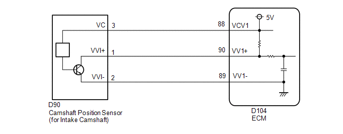
WIRING DIAGRAM
CAUTION / NOTICE / HINT
HINT:
Read Freeze Frame Data using the GTS. The ECM records vehicle and driving condition information as Freeze Frame Data the moment a DTC is stored. When troubleshooting, Freeze Frame Data can help determine if the vehicle was moving or stationary, if the engine was warmed up or not, if the air fuel ratio was lean or rich, and other data from the time the malfunction occurred.
PROCEDURE
| 1. | CHECK HARNESS AND CONNECTOR |
HINT:
Make sure that the connector is properly connected. If it is not, securely connect it and check for DTCs again.
(a) Disconnect the camshaft position sensor (for intake camshaft) connector.
(b) Turn the ignition switch to ON.
| (c) Measure the voltage according to the value(s) in the table below. Standard Voltage:
|
|
(d) Turn the ignition switch off and wait for at least 30 seconds.
(e) Measure the resistance according to the value(s) in the table below.
Standard Resistance:
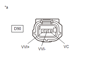
| Tester Connection | Condition | Specified Condition |
|---|---|---|
| D90-3(VC) - D90-1(VVI+) | Ignition switch off | 1.425 to 1.575 kΩ |
| D90-2(VVI-) - Body ground | Always | Below 1 Ω |
| OK |
 | REPLACE CAMSHAFT POSITION SENSOR (FOR INTAKE CAMSHAFT) |
|

| 2. | CHECK HARNESS AND CONNECTOR (CAMSHAFT POSITION SENSOR (FOR INTAKE CAMSHAFT) - ECM) |
(a) Disconnect the camshaft position sensor (for intake camshaft) connector.
(b) Disconnect the ECM connector.
(c) Measure the resistance according to the value(s) in the table below.
Standard Resistance:
| Tester Connection | Condition | Specified Condition |
|---|---|---|
| D90-1(VVI+) - D104-90(VV1+) | Always | Below 1 Ω |
| D90-2(VVI-) - D104-89(VV1-) | Always | Below 1 Ω |
| D90-3(VC) - D104-88(VCV1) | Always | Below 1 Ω |
| D90-1(VVI+) or D104-90(VV1+) - Body ground and other terminals | Always | 10 kΩ or higher |
| D90-2(VVI-) or D104-89(VV1-) - Body ground and other terminals | Always | 10 kΩ or higher |
| D90-3(VC) or D104-88(VCV1) - Body ground and other terminals | Always | 10 kΩ or higher |
| OK |
 | REPLACE ECM |
| NG |
 | REPAIR OR REPLACE HARNESS OR CONNECTOR |
 Camshaft Position Sensor "A" Bank 1 or Single Sensor No Signal (sub) (P034000)
DESCRIPTION Refer to DTC P034011. Click here
DTC No. Detection Item DTC Detection Condition Trouble Area MIL Note P034000 Camshaft Position Sensor "A" Bank 1 or Single Sensor No Signal (sub) No camshaft position sensor (for intake camshaft) signal to the sub ECM while engine running ECM Comes on SAE: P0340 MONITOR DESCRIPTION While the engine is running, when the VV1 (VV2) signal is not input to the sub CPU even though the VV1 (VV2) signal is input to the main CPU, the ECM judges that a malfunction has occurred in an internal ECM circuit, and illuminates the MIL and stores a DTC...
 Camshaft Position Sensor "A" Bank 1 or Single Sensor No Signal (P034031)
DESCRIPTION Refer to DTC P034011. Click here
DTC No. Detection Item DTC Detection Condition Trouble Area MIL Note P034031 Camshaft Position Sensor "A" Bank 1 or Single Sensor No Signal No camshaft position sensor (for intake camshaft) signal for 5 seconds at an engine speed of 600 rpm or higher (1 trip detection logic)...
Other information:
Toyota Yaris XP210 (2020-2025) Owner's Manual: Call Interrupt
A call can be interrupted to receive an incoming call from a third party. When is selected or the pick-up button on the steering wheel is pressed, the current call is held and the system switches to the new incoming call. When is selected, the current call is ended and the system switches to the new incoming call (GSM network only)...
Toyota Yaris XP210 (2020-2025) Reapir and Service Manual: Disassembly
DISASSEMBLY PROCEDURE 1. REMOVE BACK-UP LIGHT ASSEMBLY Click here 2. REMOVE NO. 2 LUGGAGE ROOM WIRE (a) Disengage the clamps to remove the No. 2 luggage room wire. 3. REMOVE REFLEX REFLECTOR ASSEMBLY LH (a) Remove the screw. (b) Disengage the claw and guide to remove the reflex reflector assembly LH...
Categories
- Manuals Home
- Toyota Yaris Owners Manual
- Toyota Yaris Service Manual
- Key Battery Replacement
- Removal
- Diagnostic Trouble Code Chart
- New on site
- Most important about car
Front Seat Belt Pretensioners
The front seat belt pretensioners are designed to deploy in moderate or severe frontal, near frontal collisions.
In addition, the pretensioners operate when a side collision or a rollover accident is detected. The pretensioners operate differently depending on what types of air bags are equipped. For more details about the seat belt pretensioner operation, refer to the SRS Air Bag Deployment Criteria.