Toyota Yaris: Rear Bumper / Disassembly
DISASSEMBLY
PROCEDURE
1. REMOVE BACK-UP LIGHT ASSEMBLY
Click here
.gif)
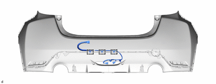
2. REMOVE NO. 2 LUGGAGE ROOM WIRE
(a) Disengage the clamps to remove the No. 2 luggage room wire.
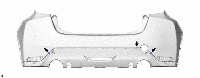
3. REMOVE REFLEX REFLECTOR ASSEMBLY LH
| (a) Remove the screw. |
|
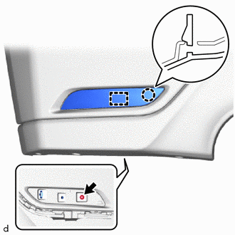
(b) Disengage the claw and guide to remove the reflex reflector assembly LH.
4. REMOVE REFLEX REFLECTOR ASSEMBLY RH
HINT:
Use the same procedure as for the LH side.
5. REMOVE NO. 1 REAR BUMPER PLATE
| (a) Disengage the claws and hook to remove the No. 1 rear bumper plate. |
|
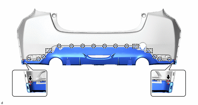
6. REMOVE REAR BUMPER LOWER COVER
| (a) Disengage the claws and hook to remove the rear bumper lower cover. |
|
7. REMOVE REAR BUMPER CENTER GUARD
(a) Remove the 3 clips.
(b) Remove the 2 screws.
(c) Disengage the claws and guides to remove the rear bumper center guard.
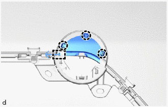
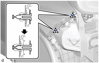
8. REMOVE REAR BUMPER SIDE RETAINER LH
| (a) Disengage the clips as shown in the illustration. |
|
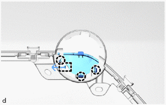
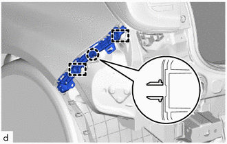
| (b) Disengage the claw and guides to remove the rear bumper side retainer LH. |
|
9. REMOVE REAR BUMPER SIDE RETAINER RH
HINT:
Use the same procedure as for the LH side.
10. REMOVE REAR COMBINATION LIGHT ASSEMBLY LH
Click here
11. REMOVE REAR COMBINATION LIGHT ASSEMBLY RH
HINT:
Use the same procedure as for the LH side.
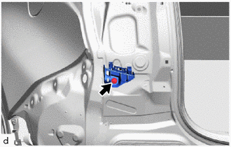
12. REMOVE REAR BUMPER SIDE SUPPORT LH
| (a) Remove the screw and rear bumper side support LH. |
|
13. REMOVE REAR BUMPER SIDE SUPPORT RH
HINT:
Use the same procedure as for the LH side.
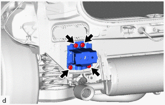
14. REMOVE REAR BUMPER ARM SUB-ASSEMBLY LH
| (a) Remove the 4 bolts and rear bumper arm sub-assembly LH. |
|
15. REMOVE REAR BUMPER ARM SUB-ASSEMBLY RH
HINT:
Use the same procedure as for the LH side.
 Removal
REMOVAL PROCEDURE 1. REMOVE REAR BUMPER SIDE SEAL LH (a) Apply protective tape around the rear bumper assembly. HINT: Use the same procedure for the RH side and LH side...
 Reassembly
REASSEMBLY PROCEDURE 1. INSTALL REAR BUMPER ARM SUB-ASSEMBLY LH (a) Install the rear bumper arm sub-assembly LH with the 4 bolts. Torque: 17 N·m {173 kgf·cm, 13 ft·lbf}
2...
Other information:
Toyota Yaris XP210 (2020-2026) Reapir and Service Manual: Installation
INSTALLATION CAUTION / NOTICE / HINT HINT: Use the same procedure for the RH side and LH side. The following procedure is for the LH side. PROCEDURE 1. INSTALL OUTER REAR VIEW MIRROR ASSEMBLY (a) Engage the clamp and claw to install the outer rear view mirror assembly...
Toyota Yaris XP210 (2020-2026) Reapir and Service Manual: Installation
INSTALLATION PROCEDURE 1. INSTALL TRANSMISSION CONTROL CABLE ASSEMBLY (a) Pass the transmission control cable assembly through the hole to the outside of the vehicle and install the transmission control cable assembly to the vehicle body with the 2 bolts...
Categories
- Manuals Home
- Toyota Yaris Owners Manual
- Toyota Yaris Service Manual
- Key Battery Replacement
- Diagnostic Trouble Code Chart
- Removal
- New on site
- Most important about car
Fuel Gauge
The fuel gauge shows approximately how much fuel is remaining in the tank when the ignition is switched ON. We recommend keeping the tank over 1/4 full.
