
Toyota Yaris: Rear Bumper / Reassembly
REASSEMBLY
PROCEDURE
1. INSTALL REAR BUMPER ARM SUB-ASSEMBLY LH
| (a) Install the rear bumper arm sub-assembly LH with the 4 bolts. Torque: 17 N·m {173 kgf·cm, 13 ft·lbf} |
|
.png)
2. INSTALL REAR BUMPER ARM SUB-ASSEMBLY RH
HINT:
Use the same procedure as for the LH side.
3. INSTALL REAR BUMPER SIDE SUPPORT LH
| (a) Install the rear bumper side support LH with the screw. |
|
.png)
4. INSTALL REAR BUMPER SIDE SUPPORT RH
HINT:
Use the same procedure as for the LH side.
5. INSTALL REAR COMBINATION LIGHT ASSEMBLY LH
Click here
.gif)
6. INSTALL REAR COMBINATION LIGHT ASSEMBLY RH
HINT:
Use the same procedure as for the LH side.
7. INSTALL REAR BUMPER SIDE RETAINER LH
| (a) Engage the guides and claw to install the rear bumper side retainer LH. |
|
.png)
| (b) Engage the clips as shown in the illustration. |
|
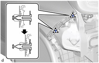
8. INSTALL REAR BUMPER SIDE RETAINER RH
HINT:
Use the same procedure as for the LH side.
9. INSTALL REAR BUMPER CENTER GUARD
(a) Engage the guides and claws to install the rear bumper center guard.
.png)
(b) Install the 2 screws.
(c) Install the 3 clips.
.png)
10. INSTALL REAR BUMPER LOWER COVER
| (a) Engage the hook and claws to install the rear bumper lower cover. |
|
.png)
11. INSTALL NO. 1 REAR BUMPER PLATE
| (a) Engage the hook and claws to install the No. 1 rear bumper plate. |
|
.png)
12. INSTALL REFLEX REFLECTOR ASSEMBLY LH
| (a) Engage the guide and claw to install the reflex reflector assembly LH. |
|
.png)
(b) Install the screw.
13. INSTALL REFLEX REFLECTOR ASSEMBLY RH
HINT:
Use the same procedure as for the LH side.
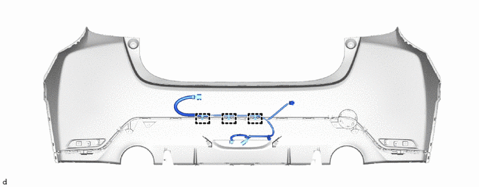
14. INSTALL NO. 2 LUGGAGE ROOM WIRE
(a) Engage the clamps to install the No. 2 luggage room wire.
15. INSTALL BACK-UP LIGHT ASSEMBLY
Click here
 Disassembly
DISASSEMBLY PROCEDURE 1. REMOVE BACK-UP LIGHT ASSEMBLY Click here
2. REMOVE NO. 2 LUGGAGE ROOM WIRE (a) Disengage the clamps to remove the No. 2 luggage room wire...
 Installation
INSTALLATION PROCEDURE 1. INSTALL REAR BUMPER ASSEMBLY (a) Connect the connector.
Install in the Direction (b) Engage the claws to install the rear bumper assembly as shown in the illustration...
Other information:
Toyota Yaris XP210 (2020-2026) Reapir and Service Manual: Installation
INSTALLATION PROCEDURE 1. INSTALL STEERING PAD SWITCH ASSEMBLY Click here 2. INSTALL NO. 1 STEERING WHEEL ORNAMENT Click here 3. ADJUST SPIRAL CABLE WITH SENSOR SUB-ASSEMBLY Click here 4. INSTALL STEERING WHEEL ASSEMBLY (a) Align the matchmarks on the steering wheel assembly and steering main shaft to install the steering wheel assembly...
Toyota Yaris XP210 (2020-2026) Owner's Manual: Troubleshooting
If you have any problems with Bluetooth®, contact our toll-free customer service center. U.S.A.Toyota Customer Experience Center Phone: 1-800-331-4331 (Toll-free) Web: http://www.toyota.com/entune CanadaToyota Canada Customer Interaction Centre Phone: 1-888-TOYOTA-8 or 1-888-869-6828 (Toll-free) Web: http://www...
Categories
- Manuals Home
- Toyota Yaris Owners Manual
- Toyota Yaris Service Manual
- Brake System Control Module "A" System Voltage System Voltage Low (C137BA2)
- How to connect USB port/Auxiliary jack
- Fuse Panel Description
- New on site
- Most important about car
Break-In Period
No special break-in is necessary, but a few precautions in the first 600 miles (1,000 km) may add to the performance, economy, and life of the vehicle.
Do not race the engine. Do not maintain one constant speed, either slow or fast, for a long period of time. Do not drive constantly at full-throttle or high engine rpm for extended periods of time. Avoid unnecessary hard stops. Avoid full-throttle starts.