Toyota Yaris: Air Conditioning System / Ambient Temperature Display System
DESCRIPTION
The thermistor assembly is installed in front of the cooler condenser assembly to detect the ambient temperature, which is used to control the automatic air conditioning system. The thermistor assembly detects fluctuations in the ambient temperature and sends it as a signal to the combination meter assembly. This data is used for controlling the cabin temperature. The resistance of the thermistor assembly changes in accordance with the ambient temperature. As the temperature decreases, the resistance increases. As the temperature increases, the resistance decreases. The combination meter assembly applies voltage (5 V) to the thermistor assembly and detects voltage changes due to changes in the resistance of the thermistor assembly.
The air conditioning amplifier assembly communicates with the combination meter assembly via CAN communication.
NOTICE:
The thermistor assembly detects the ambient temperature in its vicinity, not the ambient temperature around the vehicle. Depending on factors such as radiant heat from the engine room and the vehicle speed, the ambient temperature detected by the thermistor assembly may differ from the ambient temperature displayed on the multi-information display in the combination meter assembly. For example:
- When the vehicle is stopped or being driven at low speeds, the displayed ambient temperature will not be updated to a higher temperature to adjust for and minimize the influence of radiant heat from the engine room on the automatic air conditioning system control. When the vehicle is not being driven at low speeds, the adjustment is performed, but updating of the displayed ambient temperature to a higher temperature is delayed. The displayed ambient temperature will be updated to a lower temperature regardless of the vehicle speed.
- When the ambient temperature around the thermistor assembly suddenly changes due to any reason other than radiant heat from the engine room, such as when the vehicle enters or exits a garage or tunnel, the actual ambient temperature of the vehicle and the displayed ambient temperature may differ or changing of the displayed value may be delayed.
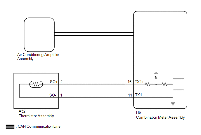
WIRING DIAGRAM
CAUTION / NOTICE / HINT
NOTICE:
-
Before starting the inspection, it is necessary to release the residual heat from the engine room (engine unit and coolant hoses, etc.) after stopping the engine and electric motor (when the vehicle is parked after being driven). Therefore, move and park the vehicle in the following type of temperature measurement location.
- A location within the vehicle service area which has a relatively low amount of environmental temperature changes in the area surrounding the vehicle.
- A location with a level surface made of a material such as concrete which transmits a relatively low amount of heat from the ground, such as concrete.
- A location with no heat influences around the vehicle to be inspected such as other vehicles with a running engine and electric motors, exhaust gas ducts installed on the exhaust pipes, stoves, etc.
-
The air conditioning system uses the CAN communication system. Inspect the communication function by following How to Proceed with Troubleshooting. Troubleshoot the air conditioning system after confirming that the communication system is functioning properly.
Click here

-
After turning the ignition switch off, waiting time may be required before disconnecting the cable from the negative (-) auxiliary battery terminal.
Click here

HINT:
When disconnecting and reconnecting the cable to the auxiliary battery terminal, there is an automatic learning function that completes learning when the respective system is used.
Click here

PROCEDURE
| 1. | CHECK FOR DTC |
(a) Check for DTCs.
Body Electrical > Air Conditioner > Trouble CodesNOTICE:
Perform the parked vehicle inspection with the ignition switch to ON. (Do not start the engine.)
| Result | Proceed to |
|---|---|
| P007011 and P007015 is not output | A |
| P007011 is output | B |
| P007015 is output | C |
| B |
 | GO TO DTC P007011 |
| C |
 | GO TO DTC P007015 |
|

| 2. | INSPECT THERMISTOR ASSEMBLY |
Click here

| NG |
 | REPLACE THERMISTOR ASSEMBLY |
|

| 3. | CHECK HARNESS AND CONNECTOR (THERMISTOR ASSEMBLY - COMBINATION METER ASSEMBLY) |
NOTICE:
During the parked vehicle inspection, perform the inspection with the ignition switch off (do not start the engine and electric motor).
(a) Disconnect the H6 combination meter assembly connector.
(b) Measure the resistance according to the value(s) in the table below.
Standard Resistance:
| Tester Connection | Condition | Specified Condition |
|---|---|---|
| A52-1 (SO-) - H6-11 (TX1-) | Always | Below 1 Ω |
| A52-2 (SO+) - H6-16 (TX1+) | Always | Below 1 Ω |
| A52-1 (SO-) or H6-11 (TX1-) - Other terminals and body ground | Always | 10 kΩ or higher |
| A52-2 (SO+) or H6-16 (TX1+) - Other terminals and body ground | Always | 10 kΩ or higher |
| NG |
 | REPAIR OR REPLACE HARNESS OR CONNECTOR |
|

| 4. | CHECK VALUE OF AMBIENT TEMPERATURE DETECTED BY THERMISTOR ASSEMBLY |
(a) Disconnect the cable from the negative (-) auxiliary battery terminal and wait for at least 90 seconds.
HINT:
The air conditioning amplifier assembly reads and memorizes the thermistor assembly (ambient temperature sensor) detection value (THO) from before the ignition switch was turned off for 1 hour after turning the ignition switch off. Therefore, it is necessary to switch off the air conditioning amplifier assembly internal power source and clear the stored values from before the ignition switch was turned off.
(b) Connect the cable to the negative (-) auxiliary battery terminal.
(c) Measure and make a note of the ambient temperature near the thermistor assembly using a thermometer.
NOTICE:
- Perform the following procedure with the ignition switch to ON.
- Wait at least 6 minutes for the values of the thermistor assembly and thermometer to become stable before taking a measurement.
- Hold the thermometer 50 mm (1.97 in.) from the thermistor assembly with its sensing portion at the same height and perpendicular to the thermistor assembly.
- Hold the sensor only by its connector. Touching the sensing portion may change the resistance value.
- When measuring the ambient temperature with a thermometer, do not move the thermometer, touch the sensing portion or allow it to contact the vehicle body.
(d) Make a note of the ambient temperature displayed on the multi-information display in the combination meter assembly.
(e) Compare the value of the ambient temperature measured by the thermometer and the thermistor assembly.
OK:
The value of the ambient temperature measured by the thermometer and the thermistor assembly are almost the same.
| OK |
 | END |
| NG |
 | REPLACE AIR CONDITIONING AMPLIFIER ASSEMBLY |
 Blower Motor Circuit
DESCRIPTION The blower motor with fan sub-assembly is operated by signals from the air conditioning amplifier assembly. Blower motor speed signals are transmitted in accordance with changes in the duty ratio...
 A/C Switch Indicator does not Turn On
DESCRIPTION If none of the switch indicators on the air conditioning control assembly illuminate, the following factors may be the cause. Symptom Factor A/C switch indicator does not illuminate
Vehicle control history (RoB)
Air conditioning amplifier assembly malfunction
Air conditioning control assembly malfunction
A/C switch malfunction
A/C switch indicator malfunction (including when indicator turned off without switch operation)
Servo motor initialization (incomplete)
Mechanical locking of damper and damper link
Refrigerant pressure is extremely low
Low detected ambient temperature (including thermistor assembly malfunction)
PROCEDURE 1...
Other information:
Toyota Yaris XP210 (2020-2026) Owner's Manual: Daytime Running Lights
Some countries require moving vehicles to have their lights on (daytime running lights) during the daytime. The daytime running lights turn on automatically when the vehicle starts moving. They turn off when the parking brake is operated or the shift lever is shifted to the P position (automatic transaxle vehicle)...
Toyota Yaris XP210 (2020-2026) Reapir and Service Manual: Evaporative Emission System Purge Control Valve "A" Circuit Open (P044313)
DESCRIPTION To reduce hydrocarbon (HC) emissions, evaporated fuel from the fuel tank is routed through a charcoal canister to the intake manifold for combustion in the cylinders. The ECM changes the duty signals to the purge VSV (Vacuum Switching Valve for Purge Control) so that the intake amount of hydrocarbon (HC) emissions is appropriate for the driving conditions (engine load, engine speed, vehicle speed, etc...
Categories
- Manuals Home
- Toyota Yaris Owners Manual
- Toyota Yaris Service Manual
- Diagnostic Trouble Code Chart
- Opening and Closing the Liftgate/Trunk Lid
- To Set Speed
- New on site
- Most important about car
Refueling
Before refueling, close all the doors, windows, and the liftgate/trunk lid, and switch the ignition OFF.
To open the fuel-filler lid, pull the remote fuel-filler lid release.
