Toyota Yaris: Air Conditioning System / Blower Motor Circuit
DESCRIPTION
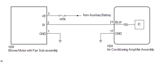
The blower motor with fan sub-assembly is operated by signals from the air conditioning amplifier assembly. Blower motor speed signals are transmitted in accordance with changes in the duty ratio.
If the airflow volume is low or the blower speed cannot be changed, the following factors may be the cause.
| Symptom | Factor |
|---|---|
| Airflow volume cannot be changed |
|
WIRING DIAGRAM
CAUTION / NOTICE / HINT
NOTICE:
Inspect the fuses for circuits related to this system before performing the following procedure.
PROCEDURE
| 1. | PERFORM ACTIVE TEST USING GTS (BLOWER LEVEL) |
(a) Perform the Active Test according to the display on the GTS.
Body Electrical > Air Conditioner > Active Test| Tester Display | Measurement Item | Control Range | Diagnostic Note |
|---|---|---|---|
| Blower Level | Blower motor with fan sub-assembly | Min.: 0 Max.: 31 | - |
| Tester Display |
|---|
| Blower Level |
| Result | Proceed to |
|---|---|
| Blower motor with fan sub-assembly does not operate | A |
| Blower motor with fan sub-assembly operates but does not change speed | B |
| B |
 | GO TO STEP 7 |
|

| 2. | CHECK HARNESS AND CONNECTOR (BLOWER MOTOR WITH FAN SUB-ASSEMBLY - POWER SOURCE) |
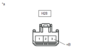
(a) Disconnect the blower motor with fan sub-assembly connector.
| (b) Measure the voltage according to the value(s) in the table below. Standard Voltage:
|
|
| NG |
 | REPAIR OR REPLACE HARNESS OR CONNECTOR |
|

| 3. | CHECK HARNESS AND CONNECTOR (BLOWER MOTOR WITH FAN SUB-ASSEMBLY - BODY GROUND) |
(a) Measure the resistance according to the value(s) in the table below.
Standard Voltage:
| Tester Connection | Condition | Specified Condition |
|---|---|---|
| H28-1 (GND) - Body ground | Always | Below 1 Ω |
| NG |
 | REPAIR OR REPLACE HARNESS OR CONNECTOR |
|

| 4. | CHECK HARNESS AND CONNECTOR (BLOWER MOTOR WITH FAN SUB-ASSEMBLY - AIR CONDITIONING AMPLIFIER ASSEMBLY) |
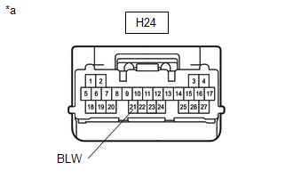
(a) Disconnect the H24 air conditioning amplifier assembly connector.
(b) Measure the resistance according to the value(s) in the table below.
Standard Resistance:
| Tester Connection | Condition | Specified Condition |
|---|---|---|
| H28-2 (SI) - H24-21 (BLW) | Always | Below 1 Ω |
| H28-2 (SI) or H24-21 (BLW) - Other terminals and body ground | Always | 10 kΩ or higher |
| NG |
 | REPAIR OR REPLACE HARNESS OR CONNECTOR |
|

| 5. | INSPECT BLOWER MOTOR WITH FAN SUB-ASSEMBLY |
(a) Connect the H28 blower motor with fan sub-assembly connector.
| (b) Measure the voltage according to the value(s) in the table below. Standard Voltage:
|
|
| NG |
 | REPLACE BLOWER MOTOR WITH FAN SUB-ASSEMBLY |
|

| 6. | INSPECT AIR CONDITIONING AMPLIFIER ASSEMBLY |
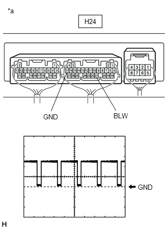
| *a | Component with harness connected (Air Conditioning Amplifier Assembly) |
(a) Connect the H24 air conditioning amplifier assembly connector.
(b) Using an oscilloscope, check the waveform.
| Item | Content |
|---|---|
| Terminal No. | H24-21 (BLW) - H24-17 (GND) |
| Tool Setting | 2 V/DIV., 1 ms./DIV. |
| Condition |
|
OK:
Waveform is similar to that shown in the illustration.
HINT:
The waveform varies with the blower speed.
| OK |
 | REPLACE BLOWER MOTOR WITH FAN SUB-ASSEMBLY |
| NG |
 | REPLACE AIR CONDITIONING AMPLIFIER ASSEMBLY |
| 7. | INSPECT AIR CONDITIONING AMPLIFIER ASSEMBLY |

| *a | Component with harness connected (Air Conditioning Amplifier Assembly) |
(a) Using an oscilloscope, check the waveform.
| Item | Content |
|---|---|
| Terminal No. | H24-21 (BLW) - H24-17 (GND) |
| Tool Setting | 2 V/DIV., 1 ms./DIV. |
| Condition |
|
OK:
Waveform is similar to that shown in the illustration.
HINT:
The waveform varies with the blower speed.
| OK |
 | REPLACE BLOWER MOTOR WITH FAN SUB-ASSEMBLY |
| NG |
 | REPLACE AIR CONDITIONING AMPLIFIER ASSEMBLY |
 Lost Communication with ECM/PCM "A" Missing Message (U010087,U013187,U014087,U015587,U016387)
DESCRIPTION These DTCs are stored when the CAN communication system is malfunctioning. DTC No. Detection Item DTC Detection Condition Trouble Area Memory U010087 Lost Communication with ECM/PCM "A" Missing Message Diagnosis Condition:
IG voltage 8...
 Ambient Temperature Display System
DESCRIPTION The thermistor assembly is installed in front of the cooler condenser assembly to detect the ambient temperature, which is used to control the automatic air conditioning system...
Other information:
Toyota Yaris XP210 (2020-2026) Owner's Manual: Tiedown Hook-Front
Remove the tiedown eyelet and the lug wrench from the luggage compartment. Wrap a jack lever or similar tool with a soft cloth to prevent damage to a painted bumper, and open the cap located on the front bumper.Remove the cap completely and store it so as not to lose it...
Toyota Yaris XP210 (2020-2026) Reapir and Service Manual: Roof Drip Side Moulding
ComponentsCOMPONENTS ILLUSTRATION *1 ROOF SIDE RAIL WEATHERSTRIP *2 ROOF SIDE RAIL WEATHERSTRIP RETAINER RemovalREMOVAL CAUTION / NOTICE / HINT HINT: Use the same procedure for the RH and LH sides. The procedure listed below is for the LH side...
Categories
- Manuals Home
- Toyota Yaris Owners Manual
- Toyota Yaris Service Manual
- Adjustment
- G16e-gts (engine Mechanical)
- Engine Start Function When Key Battery is Dead
- New on site
- Most important about car
Liftgate/Trunk Lid
WARNING
Never allow a person to ride in the luggage compartment/trunk
Allowing a person to ride in the luggage compartment/trunk is dangerous. The person in the luggage compartment/trunk could be seriously injured or killed during sudden braking or a collision.
Do not drive with the liftgate/trunk lid open