Toyota Yaris: Rear Bumper / Installation
INSTALLATION
PROCEDURE
1. INSTALL REAR BUMPER ASSEMBLY
(a) Connect the connector.
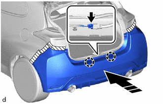
.png) | Install in the Direction |
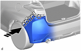
(b) Engage the claws to install the rear bumper assembly as shown in the illustration.
(c) Engage the claws to install the rear bumper assembly as shown in the illustration.
HINT:
Use the same procedure for the RH side and LH side.
|
| Install in the Direction |
(d) Install the 2 clips.
(e) Install the 2 rear bumper cushions.
2. INSTALL REAR BUMPER SIDE SEAL LH
(a) Install the rear bumper side seal LH with 5 clips and nut.
(b) Remove the protective tape.
3. INSTALL REAR BUMPER SIDE SEAL RH
HINT:
Use the same procedure as for the LH side.
 Reassembly
REASSEMBLY PROCEDURE 1. INSTALL REAR BUMPER ARM SUB-ASSEMBLY LH (a) Install the rear bumper arm sub-assembly LH with the 4 bolts. Torque: 17 N·m {173 kgf·cm, 13 ft·lbf}
2...
 Rear Spoiler
..
Other information:
Toyota Yaris XP210 (2020-2026) Reapir and Service Manual: Tire And Wheel
C..
Toyota Yaris XP210 (2020-2026) Reapir and Service Manual: Electronic Circuit Inspection Procedure
ELECTRONIC CIRCUIT INSPECTION PROCEDURE BASIC INSPECTION (a) WHEN MEASURING RESISTANCE OF ELECTRONIC PARTS (1) Unless otherwise stated, all resistance measurements are standard values measured at an ambient temperature of 20°C (68°F). Resistance measurements may be inaccurate if measured at high temperatures, i...
Categories
- Manuals Home
- Toyota Yaris Owners Manual
- Toyota Yaris Service Manual
- Brake System Control Module "A" System Voltage System Voltage Low (C137BA2)
- Adjustment
- Opening and Closing the Liftgate/Trunk Lid
- New on site
- Most important about car
Supplemental Restraint System (SRS) Precautions
The front and side supplemental restraint systems (SRS) include different types of air bags. Please verify the different types of air bags which are equipped on your vehicle by locating the “SRS AIRBAG” location indicators. These indicators are visible in the area where the air bags are installed.
The air bags are installed in the following locations:
The steering wheel hub (driver air bag) The front passenger dashboard (front passenger air bag) The outboard sides of the front seatbacks (side air bags) The front and rear window pillars, and the roof edge along both sides (curtain air bags)