Toyota Yaris: Rear Bumper / Removal
REMOVAL
PROCEDURE
1. REMOVE REAR BUMPER SIDE SEAL LH
(a) Apply protective tape around the rear bumper assembly.
HINT:
Use the same procedure for the RH side and LH side.
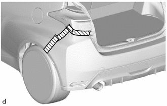
.png) | Protective Tape |
| (b) Remove the 5 clips and nut to remove the rear bumper side seal LH. |
|
2. REMOVE REAR BUMPER SIDE SEAL RH
HINT:
Use the same procedure as for the LH side.
3. REMOVE REAR BUMPER ASSEMBLY
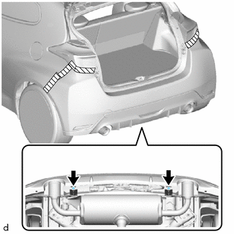
| (a) Remove the 2 rear bumper cushions. |
|
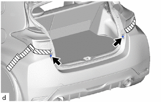
| (b) Remove the 2 clips. |
|
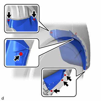
(c) Disengage the claws to separate the rear bumper assembly as shown in the illustration.
HINT:
Use the same procedure for the RH side and LH side.
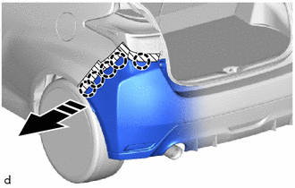
.png) | Separate in this Direction |
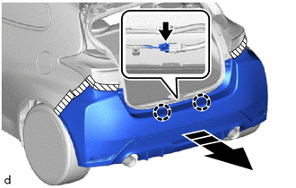
(d) Disengage the claws to pull back the rear bumper assembly as shown in the illustration.
|
| Pull back in this Direction |
(e) Disconnect the connector to remove the rear bumper assembly.
 Components
COMPONENTS ILLUSTRATION
*1 REAR BUMPER SIDE SEAL RH *2 REAR BUMPER SIDE SEAL LH *3 REAR BUMPER ASSEMBLY - - ILLUSTRATION
*1 BACK-UP LIGHT ASSEMBLY *2 NO...
 Disassembly
DISASSEMBLY PROCEDURE 1. REMOVE BACK-UP LIGHT ASSEMBLY Click here
2. REMOVE NO. 2 LUGGAGE ROOM WIRE (a) Disengage the clamps to remove the No. 2 luggage room wire...
Other information:
Toyota Yaris XP210 (2020-2026) Reapir and Service Manual: Inspection
INSPECTION PROCEDURE 1. INSPECT FUEL PUMP (a) Measure the resistance according to the value(s) in the table below. Standard Resistance: Tester Connection Specified Condition U - V 0.05 to 3.0 Ω V - W 0.05 to 3.0 Ω U - W 0...
Toyota Yaris XP210 (2020-2026) Reapir and Service Manual: Rear Window Defogger System does not Operate
DESCRIPTION An operation request signal is sent to the air conditioning amplifier assembly via LIN communication when the rear window defogger switch (air conditioning control assembly) is operated. When the air conditioning amplifier assembly receives the signal, it sends an operation request signal via CAN communication to the main body ECU (multiplex network body ECU)...
Categories
- Manuals Home
- Toyota Yaris Owners Manual
- Toyota Yaris Service Manual
- Adjustment
- Opening and Closing the Liftgate/Trunk Lid
- Auto Lock/Unlock Function
- New on site
- Most important about car
Fuel-Filler Lid and Cap
WARNING
When removing the fuel-filler cap, loosen the cap slightly and wait for any hissing to stop, then remove it
Fuel spray is dangerous. Fuel can burn skin and eyes and cause illness if ingested. Fuel spray is released when there is pressure in the fuel tank and the fuel-filler cap is removed too quickly.