Toyota Yaris: Sfi System / Camshaft Position Sensor "A" Bank 1 or Single Sensor No Signal (P034031)
DESCRIPTION
Refer to DTC P034011.
Click here

| DTC No. | Detection Item | DTC Detection Condition | Trouble Area | MIL | Note |
|---|---|---|---|---|---|
| P034031 | Camshaft Position Sensor "A" Bank 1 or Single Sensor No Signal | No camshaft position sensor (for intake camshaft) signal for 5 seconds at an engine speed of 600 rpm or higher (1 trip detection logic). * |
| Comes on | SAE: P0340 |
*: When the engine is being stopped or started automatically by stop and start system control, the ECM does not monitor the camshaft position sensor signal.
-
Reference: Inspection using an oscilloscope.
Click here

MONITOR DESCRIPTION
If no pulse signal is transmitted by the camshaft position sensor (for intake camshaft) despite the camshaft rotating, the ECM interprets this as a malfunction of the sensor.
MONITOR STRATEGY
| Required Sensors/Components (Main) | Camshaft position sensor |
| Required Sensors/Components (Related) | Crankshaft position sensor |
| Frequency of Operation | Continuous |
CONFIRMATION DRIVING PATTERN
- Connect the GTS to the DLC3.
- Turn the ignition switch to ON.
- Turn the GTS on.
- Clear the DTCs (even if no DTCs are stored, perform the clear DTC procedure).
- Turn the ignition switch off and wait for at least 30 seconds.
- Start the engine [A].
- Idle the engine for 10 seconds or more [B].
- Turn the GTS on.
- Enter the following menus: Powertrain / Engine / Trouble Codes [C].
-
Read the pending DTCs.
HINT:
- If a pending DTC is output, the system is malfunctioning.
- If a pending DTC is not output, perform the following procedure.
- Enter the following menus: Powertrain / Engine / Utility / All Readiness.
- Input the DTC: P034031.
-
Check the DTC judgment result.
GTS Display
Description
NORMAL
- DTC judgment completed
- System normal
ABNORMAL
- DTC judgment completed
- System abnormal
INCOMPLETE
- DTC judgment not completed
- Perform driving pattern after confirming DTC enabling conditions
HINT:
- If the judgment result is NORMAL, the system is normal.
- If the judgment result is ABNORMAL, the system is malfunctioning.
- If the judgment result is INCOMPLETE, perform steps [B] through [C] again.
WIRING DIAGRAM
Refer to DTC P034011.
Click here

CAUTION / NOTICE / HINT
HINT:
- Read Freeze Frame Data using the GTS. The ECM records vehicle and driving condition information as Freeze Frame Data the moment a DTC is stored. When troubleshooting, Freeze Frame Data can help determine if the vehicle was moving or stationary, if the engine was warmed up or not, if the air fuel ratio was lean or rich, and other data from the time the malfunction occurred.
- If no problem is found through this diagnostic troubleshooting procedure, there may be a mechanical problem with the engine.
PROCEDURE
| 1. | CHECK HARNESS AND CONNECTOR |
HINT:
Make sure that the connector is properly connected. If it is not, securely connect it and check for DTCs again.
(a) Disconnect the camshaft position sensor (for intake camshaft) connector.
(b) Turn the ignition switch to ON.
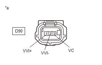
| (c) Measure the voltage according to the value(s) in the table below. Standard Voltage:
|
|
(d) Turn the ignition switch off and wait for at least 30 seconds.
(e) Measure the resistance according to the value(s) in the table below.
Standard Resistance:
| Tester Connection | Condition | Specified Condition |
|---|---|---|
| D90-3(VC) - D90-1(VVI+) | Ignition switch off | 1.425 to 1.575 kΩ |
| D90-2(VVI-) - Body ground | Always | Below 1 Ω |
| NG |
 | GO TO STEP 4 |
|

| 2. | CHECK SENSOR INSTALLATION AND CONDUCT VISUAL INSPECTION (CAMSHAFT POSITION SENSOR (FOR INTAKE CAMSHAFT)) |
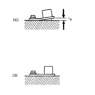
| *a | Clearance |
(a) Visually check the camshaft position sensor (for intake camshaft) for damage.
(b) Check the camshaft position sensor (for intake camshaft) installation condition.
OK:
The camshaft position sensor (for intake camshaft) does not have any damage and is installed properly.
| NG |
 | SECURELY REINSTALL CAMSHAFT POSITION SENSOR (FOR INTAKE CAMSHAFT) |
|

| 3. | INSPECT INTAKE CAMSHAFT (TIMING ROTOR) |
(a) Check the timing rotor of the intake camshaft.
OK:
Camshaft timing rotor does not have any cracks or deformation.
HINT:
Perform "Inspection After Repair" after replacing the intake camshaft.
Click here

| OK |
 | REPLACE CAMSHAFT POSITION SENSOR (FOR INTAKE CAMSHAFT) |
| NG |
 | REPLACE INTAKE CAMSHAFT |
| 4. | CHECK HARNESS AND CONNECTOR (CAMSHAFT POSITION SENSOR (FOR INTAKE CAMSHAFT) - ECM) |
(a) Disconnect the camshaft position sensor (for intake camshaft) connector.
(b) Disconnect the ECM connector.
(c) Measure the resistance according to the value(s) in the table below.
Standard Resistance:
| Tester Connection | Condition | Specified Condition |
|---|---|---|
| D90-1(VVI+) - D104-90(VV1+) | Always | Below 1 Ω |
| D90-2(VVI-) - D104-89(VV1-) | Always | Below 1 Ω |
| D90-3(VC) - D104-88(VCV1) | Always | Below 1 Ω |
| D90-1(VVI+) or D104-90(VV1+) - Body ground and other terminals | Always | 10 kΩ or higher |
| D90-2(VVI-) or D104-89(VV1-) - Body ground and other terminals | Always | 10 kΩ or higher |
| D90-3(VC) or D104-88(VCV1) - Body ground and other terminals | Always | 10 kΩ or higher |
| OK |
 | REPLACE ECM |
| NG |
 | REPAIR OR REPLACE HARNESS OR CONNECTOR |
 Camshaft Position Sensor "A" Bank 1 or Single Sensor Circuit Short to Ground (P034011,P034015)
DESCRIPTION The camshaft position sensor (for intake camshaft) (VV1 signal) consists of a magnet and MRE (Magneto-Resistive Element). The intake camshaft has a timing rotor for the camshaft position sensor...
 Camshaft Position Sensor "B" Bank 1 No Signal (sub) (P036500)
DESCRIPTION Refer to DTC P036511. Click here
DTC No. Detection Item DTC Detection Condition Trouble Area MIL Note P036500 Camshaft Position Sensor "B" Bank 1 No Signal (sub) No camshaft position sensor (for exhaust camshaft) signal to the sub ECM while engine running ECM Comes on SAE: P0365 MONITOR DESCRIPTION While the engine is running, when the EV1 (EV2) signal is not input to the sub CPU even though the EV1 (EV2) signal is input to the main CPU, the ECM judges that a malfunction has occurred in an internal ECM circuit, and illuminates the MIL and stores a DTC...
Other information:
Toyota Yaris XP210 (2020-2025) Reapir and Service Manual: Removal
REMOVAL CAUTION / NOTICE / HINT The necessary procedures (adjustment, calibration, initialization, or registration) that must be performed after parts are removed and installed, or replaced during the central gateway ECU (network gateway ECU) removal/installation are shown below...
Toyota Yaris XP210 (2020-2025) Reapir and Service Manual: Gf1a Transfer Oil
ComponentsCOMPONENTS ILLUSTRATION *1 NO. 1 ENGINE UNDER COVER ASSEMBLY *2 TRANSFER FILLER PLUG *3 TRANSFER DRAIN PLUG *4 GASKET Tightening torque for "Major areas involving basic vehicle performance such as moving/turning/stopping": N*m (kgf*cm, ft...
Categories
- Manuals Home
- Toyota Yaris Owners Manual
- Toyota Yaris Service Manual
- Diagnostic Trouble Code Chart
- To Set Speed
- Immobilizer System
- New on site
- Most important about car
Keys

To use the auxiliary key, press the knob and pull out the auxiliary key from the smart key.
