Toyota Yaris: Network Gateway Ecu / Removal
REMOVAL
CAUTION / NOTICE / HINT
The necessary procedures (adjustment, calibration, initialization, or registration) that must be performed after parts are removed and installed, or replaced during the central gateway ECU (network gateway ECU) removal/installation are shown below.
Necessary Procedure After Parts Removed/Installed/Replaced| Replacement Part or Procedure | Necessary Procedures | Effects/Inoperative when not performed | Link |
|---|---|---|---|
| Central gateway ECU (network gateway ECU) | Update ECU security key | - |
|

HINT:
When the cable is disconnected / reconnected to the auxiliary battery terminal, systems temporarily stop operating. However, each system has a function that completes learning the first time the system is used.
-
Learning completes when vehicle is driven
Effect/Inoperative Function When Necessary Procedures are not Performed
Necessary Procedures
Link
Lane tracing assist system
Drive the vehicle straight ahead at 35 km/h (22 mph) or more for 5 second or more.

Pre-collision system
Stop and start system
Drive the vehicle until stop and start control is permitted (approximately 5 to 60 minutes)

-
Learning completes when vehicle is operated normally
Effect/Inoperative Function When Necessary Procedures are not Performed
Necessary Procedures
Link
Power door lock control system
- Back door opener
Perform door unlock operation with door control switch or electrical key transmitter sub-assembly switch.

Air conditioning system
After the ignition switch is turned to ON, the servo motor standard position is recognized.
-
PROCEDURE
1. PRECAUTION
NOTICE:
After turning the ignition switch off, waiting time may be required before disconnecting the cable from the negative (-) auxiliary battery terminal.
Click here

2. DISCONNECT CABLE FROM NEGATIVE AUXILIARY BATTERY TERMINAL
Click here

3. REMOVE CENTER LOWER INSTRUMENT COVER
Click here

4. REMOVE LOWER INSTRUMENT PANEL FINISH PANEL
Click here

5. REMOVE SWITCH HOLE BASE SUB-ASSEMBLY
Click here

6. REMOVE SHIFT LEVER KNOB SUB-ASSEMBLY
Click here

7. REMOVE CONSOLE BOX ASSEMBLY
Click here

8. REMOVE FRONT DOOR SCUFF PLATE RH
HINT:
Use the same procedure as for the LH side.
Click here

9. REMOVE COWL SIDE TRIM BOARD RH
HINT:
Use the same procedure as for the LH side.
Click here

10. REMOVE NO. 2 INSTRUMENT PANEL UNDER COVER SUB-ASSEMBLY
Click here

11. DISCONNECT FRONT DOOR OPENING TRIM WEATHERSTRIP RH
HINT:
Use the same procedure as for the LH side.
Click here

12. REMOVE NO. 1 INSTRUMENT SIDE PANEL
Click here

13. REMOVE GLOVE COMPARTMENT DOOR ASSEMBLY
Click here

14. REMOVE LOWER NO. 2 INSTRUMENT PANEL FINISH PANEL
Click here

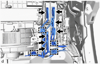
15. REMOVE ECU INTEGRATION BOX RH
| (a) Disengage clamps and disconnect the 7 connectors. |
|
| (b) Remove the bolt and 2 nuts. |
|
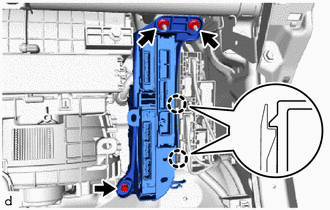
(c) Disengage the claws to remove the ECU integration box RH.
16. REMOVE CENTRAL GATEWAY ECU (NETWORK GATEWAY ECU)
(a) Disengage the claws to remove the central gateway ECU (network gateway ECU) as shown in the illustration.
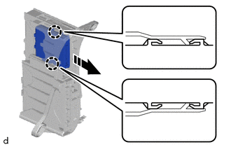
 | Remove in this Direction |
NOTICE:
- If the ECU integration box LH is deformed or damaged, replace it.
- Do not bend the claws more than necessary.
 Components
COMPONENTS ILLUSTRATION
*1 COWL SIDE TRIM BOARD RH *2 FRONT DOOR SCUFF PLATE RH *3 FRONT DOOR OPENING TRIM WEATHERSTRIP RH *4 GLOVE COMPARTMENT DOOR ASSEMBLY *5 LOWER NO...
 Installation
INSTALLATION CAUTION / NOTICE / HINT NOTICE: After performing the update ECU security key procedure, make sure to perform the initialization procedure for when the cable has been disconnected and reconnected to the negative (-) auxiliary battery terminal...
Other information:
Toyota Yaris XP210 (2020-2026) Reapir and Service Manual: Dtc Check / Clear
DTC CHECK / CLEAR DTC CHECK (a) Operate the GTS to read the DTCs. Chassis > Brake > Trouble Codes (b) Check the details of the DTCs. NOTICE: Make sure to clear the DTCs after repair. Freeze frame data is stored for each of the latest result DTCs and confirmed DTCs...
Toyota Yaris XP210 (2020-2026) Reapir and Service Manual: Horn Circuit
DESCRIPTION When the theft deterrent system is switched from the armed state to the alarm sounding state, the main body ECU (multiplex network body ECU) transmits a signal to cause the horn to sound at intervals of 0.4 seconds. WIRING DIAGRAM CAUTION / NOTICE / HINT NOTICE: If the main body ECU (multiplex network body ECU) is replaced, refer to the Registration...
Categories
- Manuals Home
- Toyota Yaris Owners Manual
- Toyota Yaris Service Manual
- Key Battery Replacement
- Fuel Gauge
- Battery Monitor Module General Electrical Failure (P058A01)
- New on site
- Most important about car
Supplemental Restraint System (SRS) Precautions
The front and side supplemental restraint systems (SRS) include different types of air bags. Please verify the different types of air bags which are equipped on your vehicle by locating the “SRS AIRBAG” location indicators. These indicators are visible in the area where the air bags are installed.
The air bags are installed in the following locations:
The steering wheel hub (driver air bag) The front passenger dashboard (front passenger air bag) The outboard sides of the front seatbacks (side air bags) The front and rear window pillars, and the roof edge along both sides (curtain air bags)