Toyota Yaris: Outer Rear View Mirror / Removal
REMOVAL
CAUTION / NOTICE / HINT
HINT:
- Use the same procedure for the RH side and LH side.
- The following procedure is for the LH side.
PROCEDURE
1. REMOVE FRONT DOOR LOWER FRAME BRACKET GARNISH
Click here
.gif)
2. REMOVE MULTIPLEX NETWORK MASTER SWITCH ASSEMBLY WITH FRONT ARMREST BASE UPPER PANEL (for Driver Side)
Click here
3. REMOVE POWER WINDOW REGULATOR SWITCH ASSEMBLY WITH FRONT ARMREST BASE UPPER PANEL (for Front Passenger Side)
Click here
4. REMOVE FRONT DOOR TRIM GARNISH
Click here
5. REMOVE FRONT DOOR TRIM BOARD SUB-ASSEMBLY
Click here
6. REMOVE FRONT DOOR GLASS INNER WEATHERSTRIP
Click here
7. REMOVE OUTER REAR VIEW MIRROR ASSEMBLY
| (a) Disconnect the connector. |
|
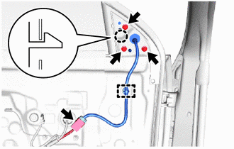
(b) Remove the 3 bolts.
(c) Disengage the claw and clamp to remove the outer rear view mirror assembly.
 Components
COMPONENTS ILLUSTRATION
*A for Front Passenger Side *B for Driver Side *1 FRONT DOOR LOWER FRAME BRACKET GARNISH *2 MULTIPLEX NETWORK MASTER SWITCH ASSEMBLY WITH FRONT ARMREST BASE UPPER PANEL *3 POWER WINDOW REGULATOR SWITCH ASSEMBLY WITH FRONT ARMREST BASE UPPER PANEL *4 FRONT DOOR TRIM GARNISH *5 FRONT DOOR TRIM BOARD SUB-ASSEMBLY *6 FRONT DOOR GLASS INNER WEATHERSTRIP *7 OUTER REAR VIEW MIRROR ASSEMBLY - -
N*m (kgf*cm, ft...
 Disassembly
DISASSEMBLY CAUTION / NOTICE / HINT HINT:
Use the same procedure for the RH side and LH side.
The following procedure is for the LH side.
PROCEDURE 1...
Other information:
Toyota Yaris XP210 (2020-2026) Reapir and Service Manual: Brake
BRAKE INSPECT BRAKE LINE PIPES AND HOSES HINT: Work in a well-lighted area. Turn the front wheels fully to the right or left before beginning the inspection. (a) Using a mirror, check the entire circumference and length of the brake lines and hoses for: Damage Wear Deformation Cracks Kinks Corrosion Leaks Twists (b) Check all the clamps for tightness and check the connections for leakage...
Toyota Yaris XP210 (2020-2026) Owner's Manual: Side Air Bags
The side air bags are mounted in the outboard sides of the front seatbacks. When the air bag crash sensors detect a side impact of greater than moderate force, the system inflates the side air bag only on the side in which the vehicle was hit...
Categories
- Manuals Home
- Toyota Yaris Owners Manual
- Toyota Yaris Service Manual
- How to use USB mode
- Engine & Hybrid System
- G16e-gts (engine Mechanical)
- New on site
- Most important about car
Supplemental Restraint System (SRS) Precautions
The front and side supplemental restraint systems (SRS) include different types of air bags. Please verify the different types of air bags which are equipped on your vehicle by locating the “SRS AIRBAG” location indicators. These indicators are visible in the area where the air bags are installed.
The air bags are installed in the following locations:
The steering wheel hub (driver air bag) The front passenger dashboard (front passenger air bag) The outboard sides of the front seatbacks (side air bags) The front and rear window pillars, and the roof edge along both sides (curtain air bags)