Toyota Yaris: Lighting System / Front Door Courtesy Switch Circuit
DESCRIPTION
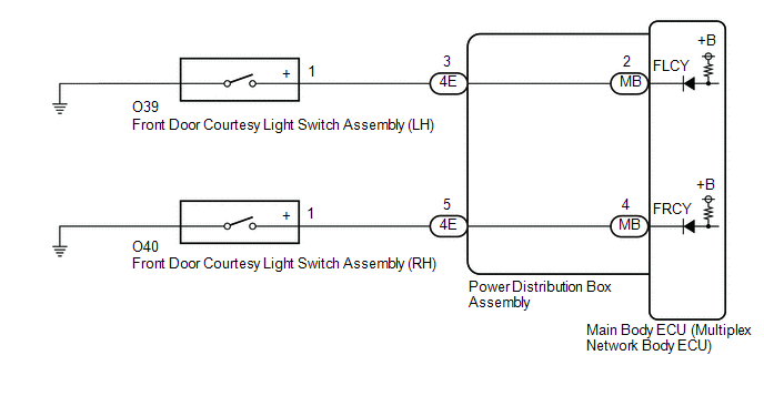
The main body ECU (multiplex network body ECU) detects the condition of the front door courtesy light switch assembly.
WIRING DIAGRAM
CAUTION / NOTICE / HINT
NOTICE:
Before replacing the main body ECU (multiplex network body ECU), refer to Registration.
Click here

PROCEDURE
| 1. | READ VALUE USING GTS |
(a) Read the Data List according to the display on the GTS.
Body Electrical > Main Body > Data List| Tester Display | Measurement Item | Range | Normal Condition | Diagnostic Note |
|---|---|---|---|---|
| FR Door Courtesy Switch Status | Front door courtesy light switch assembly RH signal | CLOSE or OPEN | CLOSE: Front door RH closed OPEN: Front door RH open | - |
| FL Door Courtesy Switch Status | Front door courtesy light switch assembly LH signal | CLOSE or OPEN | CLOSE: Front door LH closed OPEN: Front door LH open | - |
| Tester Display |
|---|
| FR Door Courtesy Switch Status |
| FL Door Courtesy Switch Status |
OK:
Normal conditions listed above are displayed.
| Result | Proceed to |
|---|---|
| OK | A |
| NG ("FR Door Courtesy Switch Status" is not normal) | B |
| NG ("FL Door Courtesy Switch Status" is not normal) | C |
| A |
 | PROCEED TO NEXT SUSPECTED AREA SHOWN IN PROBLEM SYMPTOMS TABLE |
| C |
 | GO TO STEP 5 |
|

| 2. | INSPECT FRONT DOOR COURTESY LIGHT SWITCH ASSEMBLY (RH) |
Click here

| NG |
 | REPLACE FRONT DOOR COURTESY LIGHT SWITCH ASSEMBLY (RH) |
|

| 3. | CHECK HARNESS AND CONNECTOR (FRONT DOOR COURTESY LIGHT SWITCH ASSEMBLY (RH) - POWER DISTRIBUTION BOX ASSEMBLY) |
(a) Disconnect the 4E power distribution box assembly connector.
(b) Measure the resistance according to the value(s) in the table below.
Standard Resistance:
| Tester Connection | Condition | Specified Condition |
|---|---|---|
| O39-1(+) - 4E-3 | Always | Below 1 Ω |
| O39-1(+) or 4E-3 - Body ground | Always | 10 kΩ or higher |
| NG |
 | REPAIR OR REPLACE HARNESS OR CONNECTOR |
|

| 4. | INSPECT POWER DISTRIBUTION BOX ASSEMBLY |
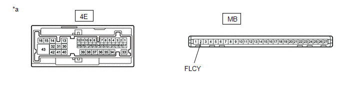
| *a | Component without harness connected (Power Distribution Box Assembly) | - | - |
(a) Remove the main body ECU (multiplex network body ECU) from the power distribution box assembly.
Click here

(b) Measure the resistance according to the value(s) in the table below.
Standard Resistance:
| Tester Connection | Condition | Specified Condition |
|---|---|---|
| 4E-3 - MB-2 (FLCY) | Always | Below 1 Ω |
| OK |
 | REPLACE MAIN BODY ECU (MULTIPLEX NETWORK BODY ECU) |
| NG |
 | REPLACE POWER DISTRIBUTION BOX ASSEMBLY |
| 5. | INSPECT FRONT DOOR COURTESY LIGHT SWITCH ASSEMBLY (LH) |
Click here

| NG |
 | REPLACE FRONT DOOR COURTESY LIGHT SWITCH ASSEMBLY RH |
|

| 6. | CHECK HARNESS AND CONNECTOR (FRONT DOOR COURTESY LIGHT SWITCH ASSEMBLY (LH) - MAIN BODY ECU (MULTIPLEX NETWORK BODY ECU)) |
(a) Disconnect the 4E power distribution box assembly connector.
(b) Measure the resistance according to the value(s) in the table below.
Standard Resistance:
| Tester Connection | Condition | Specified Condition |
|---|---|---|
| O40-1(+) - 4E-5 | Always | Below 1 Ω |
| O40-1(+) or 4E-5 - Body ground | Always | 10 kΩ or higher |
| NG |
 | REPAIR OR REPLACE HARNESS OR CONNECTOR |
|

| 7. | INSPECT POWER DISTRIBUTION BOX ASSEMBLY |
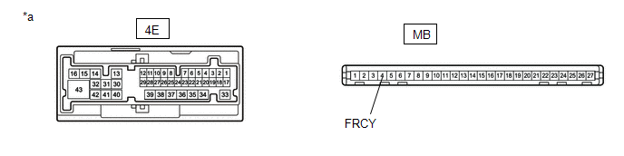
| *a | Component without harness connected (Power Distribution Box Assembly) | - | - |
(a) Remove the main body ECU (multiplex network body ECU) from the power distribution box assembly.
Click here

(b) Measure the resistance according to the value(s) in the table below.
Standard Resistance:
| Tester Connection | Condition | Specified Condition |
|---|---|---|
| 4E-5 - MB-4 (FRCY) | Always | Below 1 Ω |
| OK |
 | REPLACE MAIN BODY ECU (MULTIPLEX NETWORK BODY ECU) |
| NG |
 | REPLACE POWER DISTRIBUTION BOX ASSEMBLY |
 IG Signal Circuit
DESCRIPTION This circuit detects the ignition switch ON or off condition, and sends it to the main body ECU (multiplex network body ECU). WIRING DIAGRAM
CAUTION / NOTICE / HINT NOTICE:
Inspect the fuses for circuits related to this system before performing the following procedure...
 Back Door Courtesy Switch Circuit
DESCRIPTION The main body ECU (multiplex network body ECU) receives a back door open/closed signal from the back door courtesy light switch (back door lock assembly)...
Other information:
Toyota Yaris XP210 (2020-2026) Reapir and Service Manual: Data List / Active Test
DATA LIST / ACTIVE TEST DATA LIST HINT: Using the GTS to read the Data List allows the values or states of switches, sensors, actuators and other items to be read without removing any parts. This non-intrusive inspection can be very useful because intermittent conditions or signals may be discovered before parts or wiring is disturbed...
Toyota Yaris XP210 (2020-2026) Owner's Manual: Floor Mat
Use only floor mats designed specifically for vehicles of the same model and model year as your vehicle. When setting a floor mat, position the floor mat so that its grommets are inserted over the pointed end of the retention posts. WARNING Make sure the floor mats are hooked on the retention pins to prevent them from bunching up under the foot pedals Using a floor mat that is not secured is dangerous as it will interfere with the accelerator and brake pedal operation, which could result in an accident...
Categories
- Manuals Home
- Toyota Yaris Owners Manual
- Toyota Yaris Service Manual
- Engine Start Function When Key Battery is Dead
- Fuel Gauge
- Fuse Panel Description
- New on site
- Most important about car
Supplemental Restraint System (SRS) Precautions
The front and side supplemental restraint systems (SRS) include different types of air bags. Please verify the different types of air bags which are equipped on your vehicle by locating the “SRS AIRBAG” location indicators. These indicators are visible in the area where the air bags are installed.
The air bags are installed in the following locations:
The steering wheel hub (driver air bag) The front passenger dashboard (front passenger air bag) The outboard sides of the front seatbacks (side air bags) The front and rear window pillars, and the roof edge along both sides (curtain air bags)