Toyota Yaris: Lighting (ext) / Side Turn Signal Light Assembly
Components
COMPONENTS
ILLUSTRATION
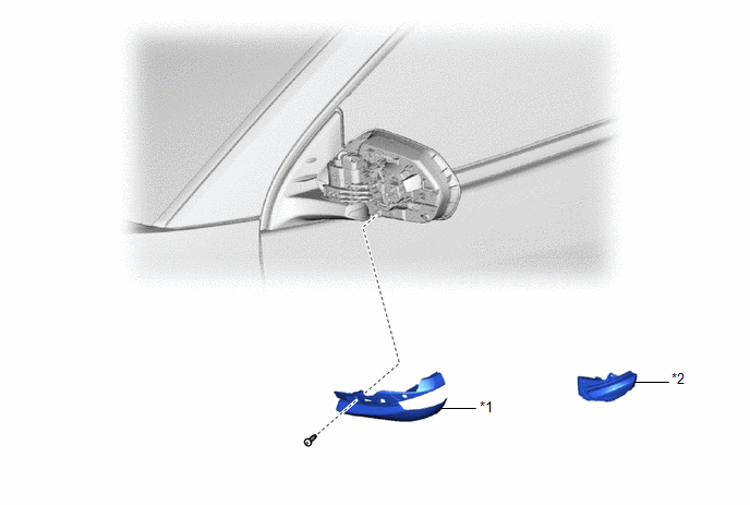
| *1 | OUTER MIRROR LOWER COVER | *2 | SIDE TURN SIGNAL LIGHT ASSEMBLY |
Removal
REMOVAL
CAUTION / NOTICE / HINT
HINT:
- Use the same procedure for the RH and LH sides.
- The procedure listed below is for the LH side.
PROCEDURE
1. REMOVE OUTER MIRROR COVER
Click here
.gif)
2. REMOVE OUTER MIRROR LOWER COVER
Click here
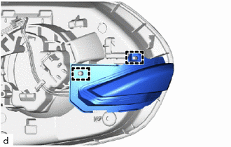
3. REMOVE SIDE TURN SIGNAL LIGHT ASSEMBLY
| (a) Disengage the guides to separate the side turn signal light assembly. |
|
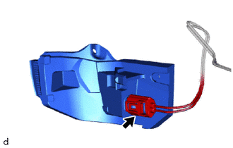
| (b) Disconnect the connector to remove the side turn signal light assembly. |
|
Inspection
INSPECTION
PROCEDURE
1. INSPECT SIDE TURN SIGNAL LIGHT ASSEMBLY LH
(a) Check that the side turn signal light assembly LH.
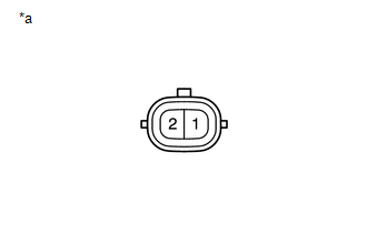
| (1) Apply auxiliary battery voltage to the side turn signal light assembly LH and check that the light comes on. OK:
If the result is not as specified, replace the side turn signal light assembly LH. |
|
2. INSPECT SIDE TURN SIGNAL LIGHT ASSEMBLY RH
(a) Check that the side turn signal light assembly RH.
| (1) Apply auxiliary battery voltage to the side turn signal light assembly RH and check that the light comes on. OK:
If the result is not as specified, replace the side turn signal light assembly RH. |
|
Installation
INSTALLATION
CAUTION / NOTICE / HINT
HINT:
- Use the same procedure for the RH and LH sides.
- The procedure listed below is for the LH side.
PROCEDURE
1. INSTALL SIDE TURN SIGNAL LIGHT ASSEMBLY
(a) Connect the connector.
| (b) Engage the guides to install the side turn signal light assembly. |
|
.png)
2. INSTALL OUTER MIRROR LOWER COVER
Click here
.gif)
3. INSTALL OUTER MIRROR COVER
Click here
 Installation
INSTALLATION CAUTION / NOTICE / HINT HINT:
Use the same procedure for the RH and LH sides.
The procedure listed below is for the LH side.
PROCEDURE 1...

Other information:
Toyota Yaris XP210 (2020-2026) Reapir and Service Manual: Removal
REMOVAL CAUTION / NOTICE / HINT HINT: When the cable is disconnected / reconnected to the auxiliary battery terminal, systems temporarily stop operating. However, each system has a function that completes learning the first time the system is used. Learning completes when vehicle is driven Effect/Inoperative Function When Necessary Procedures are not Performed Necessary Procedures Link Lane tracing assist system Drive the vehicle straight ahead at 35 km/h (22 mph) or more for 5 second or more...
Toyota Yaris XP210 (2020-2026) Reapir and Service Manual: Speed Signal Circuit
DESCRIPTION HINT: This circuit is used for the systems connected to terminal +S. This signal is not used for combination meter assembly operation. Combination meter assembly components such as the speedometer operate using data received via CAN communication...
Categories
- Manuals Home
- Toyota Yaris Owners Manual
- Toyota Yaris Service Manual
- How to connect USB port/Auxiliary jack
- Power Integration No.1 System Missing Message (B235287,B235587,B235787-B235987)
- Fuel Gauge
- New on site
- Most important about car
Turning the Engine Off
Stop the vehicle completely. Manual transaxle: Shift into neutral and set the parking brake.Automatic transaxle: Shift the selector lever to the P position and set the parking brake.
Press the push button start to turn off the engine. The ignition position is off.