Toyota Yaris: Rear Combination Light Assembly / Installation
INSTALLATION
CAUTION / NOTICE / HINT
HINT:
- Use the same procedure for the RH and LH sides.
- The procedure listed below is for the LH side.
PROCEDURE
1. INSTALL REAR COMBINATION LIGHT ASSEMBLY
| (a) Connect the 3 connectors and engage the clamp. |
|
.png)
(b) Engage the guide and pin to install the rear combination light assembly as shown in the illustration.
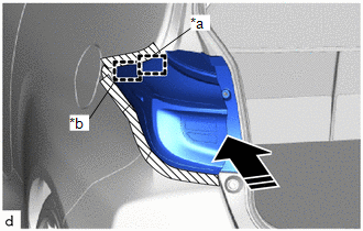
| *a | Pin |
| *b | Guide |
.png) | Install in this Direction |
(c) Install the 2 screws.
(d) Remove the protective tape.
 Reassembly
REASSEMBLY CAUTION / NOTICE / HINT HINT:
Use the same procedure for the RH and LH sides.
The procedure listed below is for the LH side.
PROCEDURE 1...
 Side Turn Signal Light Assembly
ComponentsCOMPONENTS ILLUSTRATION
*1 OUTER MIRROR LOWER COVER *2 SIDE TURN SIGNAL LIGHT ASSEMBLY RemovalREMOVAL CAUTION / NOTICE / HINT HINT:
Use the same procedure for the RH and LH sides...
Other information:
Toyota Yaris XP210 (2020-2026) Reapir and Service Manual: Data List / Active Test
DATA LIST / ACTIVE TEST DATA LIST HINT: Using the GTS to read the Data List allows the values or states of switches, sensors, actuators and other items to be read without removing any parts. This non-intrusive inspection can be very useful because intermittent conditions or signals may be discovered before parts or wiring is disturbed...
Toyota Yaris XP210 (2020-2026) Owner's Manual: Warning Light and Transaxle Ranges
Warning Light The warning light turns on when the system has a malfunction. Refer to Warning Lights. Transaxle Ranges The shift position indicator light in the combination meter illuminates. Refer to Warning/Indicator Lights. The selector lever must be in P or N to operate the starter...
Categories
- Manuals Home
- Toyota Yaris Owners Manual
- Toyota Yaris Service Manual
- Diagnostic Trouble Code Chart
- Adjustment
- Opening and Closing the Liftgate/Trunk Lid
- New on site
- Most important about car
Supplemental Restraint System (SRS) Precautions
The front and side supplemental restraint systems (SRS) include different types of air bags. Please verify the different types of air bags which are equipped on your vehicle by locating the “SRS AIRBAG” location indicators. These indicators are visible in the area where the air bags are installed.
The air bags are installed in the following locations:
The steering wheel hub (driver air bag) The front passenger dashboard (front passenger air bag) The outboard sides of the front seatbacks (side air bags) The front and rear window pillars, and the roof edge along both sides (curtain air bags)
Copyright © 2026 www.toyaris4.com