Toyota Yaris: Rear Combination Light Assembly / Reassembly
REASSEMBLY
CAUTION / NOTICE / HINT
HINT:
- Use the same procedure for the RH and LH sides.
- The procedure listed below is for the LH side.
PROCEDURE
1. INSTALL STOP LIGHT LED
(a) Install the stop light LED as shown in the illustration to install it.
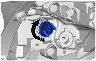
.png) | Install in this Direction |
2. INSTALL TAIL LIGHT LED
(a) Install the tail light LED as shown in the illustration to install it.
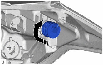
|
| Install in this Direction |
3. INSTALL REAR TURN SIGNAL LIGHT LED
(a) Install the rear turn signal light LED as shown in the illustration to install it.
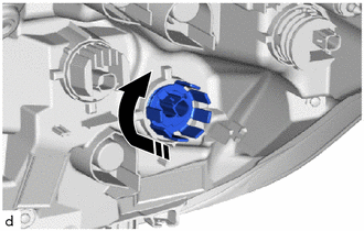
|
| Install in this Direction |
 Inspection
INSPECTION PROCEDURE 1. INSPECT STOP LIGHT LED (for LH Side) (a) Check that the stop light LED. (1) Apply auxiliary battery voltage to the stop light LED and check that the light comes on...
 Installation
INSTALLATION CAUTION / NOTICE / HINT HINT:
Use the same procedure for the RH and LH sides.
The procedure listed below is for the LH side.
PROCEDURE 1...
Other information:
Toyota Yaris XP210 (2020-2026) Reapir and Service Manual: Installation
INSTALLATION PROCEDURE 1. INSTALL FRONT STABILIZER BAR (a) Set the front stabilizer bar to the front suspension crossmember sub-assembly. NOTICE: Make sure that the identification mark is positioned on the right side of the vehicle. *a Identification Mark - - Front of the Vehicle - - (b) Install the front stabilizer bar to the front suspension crossmember sub-assembly with the 4 bolts...
Toyota Yaris XP210 (2020-2026) Owner's Manual: Fuel Consumption Display
Information regarding the fuel economy is displayed. Displays the fuel economy for the past 60 minutes. Displays the fuel economy every minute for the past 1 to 10 minutes. Displays the fuel economy every 10 minutes for the past 10 to 60 minutes...
Categories
- Manuals Home
- Toyota Yaris Owners Manual
- Toyota Yaris Service Manual
- Headlights
- To Set Speed
- Auto Lock/Unlock Function
- New on site
- Most important about car
Break-In Period
No special break-in is necessary, but a few precautions in the first 600 miles (1,000 km) may add to the performance, economy, and life of the vehicle.
Do not race the engine. Do not maintain one constant speed, either slow or fast, for a long period of time. Do not drive constantly at full-throttle or high engine rpm for extended periods of time. Avoid unnecessary hard stops. Avoid full-throttle starts.
Copyright © 2026 www.toyaris4.com