Toyota Yaris: Sfi System / Crankshaft Position - Camshaft Position Correlation Bank 1 Sensor A (P001600,P001700)
DESCRIPTION
In the VVT (Variable Valve Timing) system, the appropriate intake and exhaust valve open and close timing is controlled by the ECM. The ECM performs intake and exhaust valve control by performing the following: 1) controlling the camshaft, cam timing oil control solenoid assembly, camshaft timing gear bolt (camshaft timing oil control valve) and operating the camshaft timing gear; and 2) changing the relative positions of the camshaft and crankshaft.
| DTC No. | Detection Item | DTC Detection Condition | Trouble Area | MIL | Note |
|---|---|---|---|---|---|
| P001600 | Crankshaft Position - Camshaft Position Correlation Bank 1 Sensor A | Deviation in the crankshaft position sensor signal and camshaft sensor (for intake camshaft) signal (2 trip detection logic). |
| Comes on | SAE: P0016 |
| P001700 | Crankshaft Position - Camshaft Position Correlation Bank 1 Sensor B | Deviation in the crankshaft position sensor signal and camshaft position sensor (for exhaust camshaft) signal (2 trip detection logic). |
| Comes on | SAE: P0017 |
MONITOR DESCRIPTION
To monitor the correlation of the intake camshaft position and crankshaft position, the ECM checks the VVT learned value while the engine is idling. The VVT learned value is calibrated based on the camshaft position and crankshaft position. The intake valve timing is set to the neutral position while the engine is idling. If the VVT learned value is out of the specified range in consecutive driving cycles, the ECM illuminates the MIL and stores DTC P001600.
To monitor the correlation of the exhaust camshaft position and crankshaft position, the ECM checks the VVT learned value while the engine is idling. The VVT learned value is calibrated based on the camshaft position and crankshaft position. The exhaust valve timing is set to the most advanced angle while the engine is idling. If the VVT learned value is out of the specified range in consecutive driving cycles, the ECM illuminates the MIL and stores DTC P001700.
MONITOR STRATEGY
| Required Sensors/Components (Main) | Camshaft timing gear assembly Camshaft timing exhaust gear assembly |
| Required Sensors/Components (Related) | Camshaft position sensor Crankshaft position sensor |
| Frequency of Operation | Continuous |
TYPICAL ENABLING CONDITIONS
| Engine speed | 500 to 1000 rpm |
CONFIRMATION DRIVING PATTERN
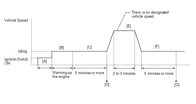
- Connect the GTS to the DLC3.
- Turn the ignition switch to ON.
- Turn the GTS on.
- Clear the DTCs (even if no DTCs are stored, perform the clear DTC procedure).
- Turn the ignition switch off and wait for at least 30 seconds.
- Turn the ignition switch to ON.
- Turn the GTS on [A].
- Start the engine and warm it up until the engine coolant temperature reaches 75°C (167°F) or higher [B].
- Idle the engine for 5 minutes or more [C].
- Enter the following menus: Powertrain / Engine / Trouble Codes [D].
-
Read the pending DTCs.
HINT:
- If a pending DTC is output, the system is malfunctioning.
- If a pending DTC is not output, perform the following procedure.
- Enter the following menus: Powertrain / Engine / Utility / All Readiness.
- Input the DTC: P001600 or P001700.
-
Check the DTC judgment result.
GTS Display
Description
NORMAL
- DTC judgment completed
- System normal
ABNORMAL
- DTC judgment completed
- System abnormal
INCOMPLETE
- DTC judgment not completed
- Perform driving pattern after confirming DTC enabling conditions
HINT:
- If the judgment result shows NORMAL, the system is normal.
- If the judgment result shows ABNORMAL, the system has a malfunction.
- If the judgment result shows INCOMPLETE, perform steps [E] through [G].
-
Drive the vehicle for 2 to 3 minutes [E].
CAUTION:
When performing the confirmation driving pattern, obey all speed limits and traffic laws.
- Idle the engine for 5 minutes or more [F].
- Enter the following menus: Powertrain / Engine / Trouble Codes [G].
-
Read the pending DTCs.
HINT:
- If a pending DTC is output, the system is malfunctioning.
- If a pending DTC is not output, perform the following procedure.
-
Check the DTC judgment result.
HINT:
- If the judgment result shows NORMAL, the system is normal.
- If the judgment result shows ABNORMAL, the system has a malfunction.
- If the judgment result shows INCOMPLETE, perform the Confirmation Driving Pattern and check the DTC judgment result again.
CAUTION / NOTICE / HINT
HINT:
- The monitor for this DTC detects when the timing chain is shifted by two teeth or more.
- Read freeze frame data using the GTS. The ECM records vehicle and driving condition information as freeze frame data the moment a DTC is stored. When troubleshooting, freeze frame data can help determine if the vehicle was moving or stationary, if the engine was warmed up or not, if the air fuel ratio was lean or rich, and other data from the time the malfunction occurred.
PROCEDURE
| 1. | CHECK FOR ANY OTHER DTCS OUTPUT (IN ADDITION TO DTC P001600 OR P001700) |
(a) Read the DTCs.
Powertrain > Engine > Trouble Codes| Result | Proceed to |
|---|---|
| P001600 or P001700 and other DTCs are output | A |
| P001600 or P001700 is output | B |
HINT:
If any DTCs other than P001600 or P001700 is output, troubleshoot those DTCs first.
| A |
 | GO TO DTC CHART |
|

| 2. | PERFORM ACTIVE TEST USING GTS (CONTROL THE INTAKE VVT OCV DUTY RATIO BANK 1 OR CONTROL THE EXHAUST VVT OCV DUTY RATIO BANK 1) |
HINT:
If the VVT system can be operated through the Active Test, it can be assumed that the VVT system is operating normally.
(a) Start the engine.
(b) Perform the Active Test. Check that the displacement angle varies.
Powertrain > Engine > Active Test| Active Test Display |
|---|
| Control the Intake VVT OCV Duty Ratio Bank 1 |
| Data List Display |
|---|
| Intake VVT Change Angle Bank 1 |
| Intake VVT OCV Control Duty Ratio Bank 1 |
OK:
Displacement angle varies.
| NG |
 | GO TO STEP 4 |
|

| 3. | CHECK ENGINE MECHANICAL SYSTEM |
(a) Check for mechanical malfunctions that affect the valve timing, such as a jumped tooth or stretching of the timing chain.
HINT:
Click here

| OK |
 | GO TO STEP 9 |
| NG |
 | REPAIR OR REPLACE MALFUNCTIONING PARTS, COMPONENT AND AREA |
| 4. | INSPECT CAM TIMING OIL CONTROL SOLENOID ASSEMBLY (FOR INTAKE CAMSHAFT) |
Click here

| NG |
 | REPLACE CAM TIMING OIL CONTROL SOLENOID ASSEMBLY (FOR INTAKE CAMSHAFT) |
|

| 5. | INSPECT CAM TIMING OIL CONTROL SOLENOID ASSEMBLY (FOR EXHAUST CAMSHAFT) |
Click here

| NG |
 | REPLACE CAM TIMING OIL CONTROL SOLENOID ASSEMBLY (FOR EXHAUST CAMSHAFT) |
|

| 6. | INSPECT CAMSHAFT TIMING GEAR BOLT (INTAKE CAMSHAFT TIMING OIL CONTROL VALVE) |
Click here

| NG |
 | REPLACE CAMSHAFT TIMING GEAR BOLT (INTAKE CAMSHAFT TIMING OIL CONTROL VALVE) |
|

| 7. | INSPECT CAMSHAFT TIMING VALVE ASSEMBLY (EXHAUST CAMSHAFT TIMING OIL CONTROL VALVE) |
Click here

| NG |
 | REPLACE CAMSHAFT TIMING VALVE ASSEMBLY (EXHAUST CAMSHAFT TIMING OIL CONTROL VALVE) |
|

| 8. | CLEAR DTC |
(a) Clear the DTCs.
Powertrain > Engine > Clear DTCs(b) Turn the ignition switch off and wait for at least 30 seconds.
|

| 9. | CHECK WHETHER DTC OUTPUT RECURS (DTC P001600 OR P001700) |
(a) Start the engine and warm it up.
(b) Drive the vehicle in accordance with the driving pattern described in the Confirmation Driving Pattern.
(c) Read the DTCs.
Powertrain > Engine > Trouble Codes| Result | Proceed to |
|---|---|
| DTCs are not output | A |
| P001600 or P001700 is output | B |
| A |
 | CHECK FOR INTERMITTENT PROBLEMS |
|

| 10. | REPLACE CAMSHAFT TIMING GEAR ASSEMBLY OR CAMSHAFT TIMING EXHAUST GEAR ASSEMBLY |
HINT:
Click here

Perform "Inspection After Repair" after replacing the camshaft timing gear assembly or camshaft timing exhaust gear assembly.
Click here

|

| 11. | CLEAR DTC |
(a) Clear the DTCs.
Powertrain > Engine > Clear DTCs(b) Turn the ignition switch off and wait for at least 30 seconds.
|

| 12. | CHECK WHETHER DTC OUTPUT RECURS (DTC P001600 OR P001700) |
(a) Start the engine and warm it up.
(b) Drive the vehicle in accordance with the driving pattern described in the Confirmation Driving Pattern.
(c) Read the DTCs.
Powertrain > Engine > Trouble Codes| Result | Proceed to |
|---|---|
| DTCs are not output | A |
| P001600 or P001700 is output | B |
| A |
 | CHECK FOR INTERMITTENT PROBLEMS |
| B |
 | REPLACE ECM |
 Camshaft Position "B" - Timing Over-Advanced or System Performance Bank 1 (P001400,P001500)
DESCRIPTION Refer to DTC P001313. Click here
DTC No. Detection Item DTC Detection Condition Trouble Area MIL Note P001400 Camshaft Position "B" - Timing Over-Advanced or System Performance Bank 1 Exhaust valve timing is stuck at a certain value when in the advance range (2 trip detection logic)...
 HO2S Heater Control Bank 1 Sensor 1 Circuit Short to Battery (P003012,P003013,P101A9E)
DESCRIPTION The air fuel ratio sensor (sensor 1) generates current that corresponds to the actual air fuel ratio. This sensor current is used to provide the ECM with feedback so that it can control the air fuel ratio...
Other information:
Toyota Yaris XP210 (2020-2026) Reapir and Service Manual: Installation
INSTALLATION CAUTION / NOTICE / HINT HINT: Use the same procedure for the RH side and LH side. The following procedure is for the LH side. PROCEDURE 1. INSTALL FRONT AXLE HUB SUB-ASSEMBLY (a) Secure the steering knuckle between aluminum plates in a vise...
Toyota Yaris XP210 (2020-2026) Reapir and Service Manual: Components
COMPONENTS ILLUSTRATION *1 RING PIN *2 STRAIGHT PIN *3 STUD BOLT *4 NO. 3 OIL NOZZLE SUB-ASSEMBLY *5 NO. 2 OIL NOZZLE SUB-ASSEMBLY *6 NO. 1 OIL NOZZLE SUB-ASSEMBLY *7 PISTON PIN *8 PISTON RING SET *9 CRANKSHAFT BEARING *10 CRANKSHAFT *11 CRANKSHAFT THRUST WASHER *12 CRANKSHAFT BEARING CAP *13 CONNECTING ROD BEARING *14 CONNECTING ROD SUB-ASSEMBLY *15 CONNECTING ROD BEARING CAP *16 CYLINDER BLOCK INSURATOR *17 NO...
Categories
- Manuals Home
- Toyota Yaris Owners Manual
- Toyota Yaris Service Manual
- How to use USB mode
- Brake System Control Module "A" System Voltage System Voltage Low (C137BA2)
- Maintenance
- New on site
- Most important about car
Break-In Period
No special break-in is necessary, but a few precautions in the first 600 miles (1,000 km) may add to the performance, economy, and life of the vehicle.
Do not race the engine. Do not maintain one constant speed, either slow or fast, for a long period of time. Do not drive constantly at full-throttle or high engine rpm for extended periods of time. Avoid unnecessary hard stops. Avoid full-throttle starts.