Toyota Yaris: Stop And Start System / Brake Booster Pressure Sensor Circuit Short to Ground (P055511,P055515)
DESCRIPTION
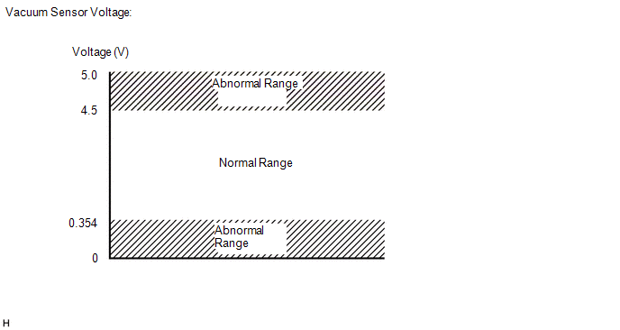
The engine stop and start ECU determines changes in the brake booster assembly pressure based on the voltage signal received from the vacuum sensor assembly in the brake booster assembly.
If the engine stop and start ECU judges that the signal received from the vacuum sensor assembly is abnormal, it stores DTC P055511 or P055515 and blinks the stop and start cancel indicator.
| DTC No. | Detection Item | DTC Detection Condition | Trouble Area | Warning Indicate | Memory | Note |
|---|---|---|---|---|---|---|
| P055511 | Brake Booster Pressure Sensor Circuit Short to Ground | Both of the following conditions are met for 2 seconds or more (1 trip detection logic):
|
| Blinks | DTC stored | SAE Code: P0557 |
| P055515 | Brake Booster Pressure Sensor Circuit Short to Battery or Open | Both of the following conditions are met for 2 seconds or more (1 trip detection logic):
|
| Blinks | DTC stored | SAE Code: P0558 |
CONFIRMATION DRIVING PATTERN
CONFIRMATION AFTER TROUBLESHOOTING
HINT:
-
If the cable is disconnected from the auxiliary battery terminal, stop and start control is prohibited until refresh charge is completed.
In this case, let the vehicle idle to complete the refresh charge. The refresh charge is complete when the Data List item Status of Auxiliary Battery Charge Control changes from "Refresh Charge Mode". (Usually, idling the engine for 5 to 60 minutes with the auxiliary battery fluid temperature at 11°C (52°F) or higher, the refresh charge will be completed.)
-
If the GTS is not available and the Data List item Status of Auxiliary Battery Charge Control cannot be checked, charge the auxiliary battery by idling the engine for approximately 5 to 60 minutes or driving the vehicle, and then drive the vehicle and check that stop and start control operates.
If the engine is started with the hood open, the system determines that a jump start has occurred. Therefore, make sure that the hood is closed before starting the engine and driving the vehicle.
- After the refresh charge completes, turn the ignition switch off, wait for at least 30 seconds, and then start the engine again. If the vehicle enters refresh charge mode again while the engine is idling, the initial refresh charge did not properly complete, so wait for the refresh charge to complete.
- Allow the engine to idle for 3 minutes after it is warmed up and check that the engine idle speed is within 50 rpm of the target idle speed.
(a) Clear the DTCs.
Powertrain > Stop and Start > Clear DTCs(b) Start the engine and allow it to idle for 15 seconds or more.
(c) Stop the engine and turn the ignition switch to ON.
(d) Turn the GTS on.
Powertrain > Stop and Start > Data List| Tester Display |
|---|
| Brake Boost Pressure |
(e) While depressing the brake pedal several times, check that the Brake Boost Pressure value changes.
(f) Check that DTCs are not output.
Powertrain > Stop and Start > Trouble CodesSTOP AND START SYSTEM OPERATION CHECK
Click here

WIRING DIAGRAM
CAUTION / NOTICE / HINT
NOTICE:
-
Before replacing the engine stop and start ECU, read the number of starter operations and write it into a new engine stop and start ECU.
Click here

-
After replacing the engine stop and start ECU, perform learning of the external backup boost converter (eco run vehicle converter assembly).
Click here

-
After replacing the engine stop and start ECU or air conditioning amplifier assembly, reset and perform learning of the air conditioning information in the engine stop and start ECU.
Click here

HINT:
-
Using the GTS, read the freeze frame data before troubleshooting. System condition information is recorded as freeze frame data the moment a DTC is stored. This information can be useful when troubleshooting.
Click here

-
For wire harness and connector inspection procedures and precautions, refer to " Click here
 "
"
-
DTCs for the stop and start system are not cleared even if the malfunction has been repaired. After repairing the malfunction, be sure to clear the DTCs.
Click here

PROCEDURE
| 1. | CHECK HARNESS AND CONNECTOR (PB TERMINAL VOLTAGE) |

| *a | Component with harness connected (Engine Stop and Start ECU) | - | - |
(a) Turn the ignition switch to ON.
(b) Measure the voltage according to the value(s) in the table below.
Standard Voltage:
| Tester Connection | Switch Condition | Specified Condition | Proceed to |
|---|---|---|---|
| A67-13 (PB) - A67-3 (BRE2) | Ignition switch ON | Higher than 0.6 V or below 4.7 V | A |
| A67-13 (PB) - A67-3 (BRE2) | Ignition switch ON | None of the above conditions are met | B |
| B |
 | USE SIMULATION METHOD TO CHECK |
|

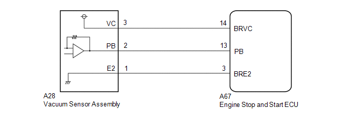
| 2. | CHECK HARNESS AND CONNECTOR (ENGINE STOP AND START ECU - VACUUM SENSOR ASSEMBLY) |
(a) Disconnect the A67 engine stop and start ECU connector.
(b) Disconnect the A28 vacuum sensor assembly connector.
(c) Measure the resistance according to the value(s) in the table below.
Standard Resistance:
| Tester Connection | Condition | Specified Condition |
|---|---|---|
| A67-13 (PB) - A28-2 (PB) | Always | Below 1 Ω |
| A67-14 (BRVC) - A28-3 (VC) | Always | Below 1 Ω |
| A67-3 (BRE2) - A28-1 (E2) | Always | Below 1 Ω |
| A67-13 (PB) - Body ground and other terminals | Always | 10 kΩ or higher |
| A67-14 (BRVC) - Body ground and other terminals | Always | 10 kΩ or higher |
| A67-3 (BRE2) - Body ground and other terminals | Always | 10 kΩ or higher |
| A28-2 (PB) - Body ground and other terminals | Always | 10 kΩ or higher |
| A28-3 (VC) - Body ground and other terminals | Always | 10 kΩ or higher |
| A28-1 (E2) - Body ground and other terminals | Always | 10 kΩ or higher |
| NG |
 | REPAIR OR REPLACE HARNESS OR CONNECTOR |
|

| 3. | CHECK ENGINE STOP AND START ECU (BRVC TERMINAL VOLTAGE) |
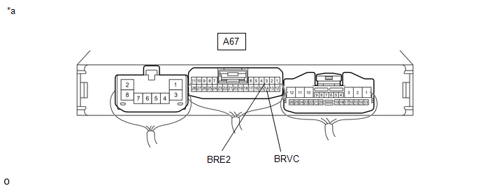
| *a | Component with harness connected (Engine Stop and Start ECU) | - | - |
(a) Turn the ignition switch to ON.
(b) Measure the voltage according to the value(s) in the table below.
Standard Voltage:
| Tester Connection | Switch Condition | Specified Condition |
|---|---|---|
| A67-14 (BRVC) - A67-3 (BRE2) | Ignition switch ON | 4.5 to 5.5 V |
| NG |
 | REPLACE ENGINE STOP AND START ECU |
|

| 4. | REPLACE VACUUM SENSOR ASSEMBLY |
Click here

|

| 5. | CLEAR DTC |
(a) Clear the DTC.
Powertrain > Stop and Start > Clear DTCs
|

| 6. | CHECK DTC OUTPUT |
(a) Start the engine and warm it up.
Powertrain > Stop and Start > Data List| Tester Display |
|---|
| Brake Boost Pressure |
(b) While depressing the brake pedal several times, check that the Brake Boost Pressure value changes.
(c) Check that no DTCs are output.
Powertrain > Stop and Start > Trouble Codes| Result | Proceed to |
|---|---|
| P055511 or P055515 is not output | A |
| DTC P055511 or P055515 is output | B |
| A |
 | END |
| B |
 | REPLACE ENGINE STOP AND START ECU |
 Brake Booster Pressure Sensor(running) (P055500,P05552A)
DESCRIPTION The engine stop and start ECU determines changes in the brake booster assembly pressure based on the voltage signal received from the vacuum sensor assembly in the brake booster assembly...
 Backup Boost Converter "A" Control CPU Signal Invalid (P060629)
DESCRIPTION The engine stop and start ECU can detect open circuits when signals such as the boost, standby request or overheating signal cannot be sent to the backup boost converter control IC from the stop and start control IC in the engine stop and start ECU...
Other information:
Toyota Yaris XP210 (2020-2025) Reapir and Service Manual: Reassembly
REASSEMBLY PROCEDURE 1. INSTALL FRONT BUMPER LOWER ABSORBER (a) Install the 4 grommets. (b) Engage the claws to install the front bumper lower absorber. (c) Install the clip and 5 screws. 2. INSTALL NO. 1 ENGINE UNDER COVER ASSEMBLY Click here 3...
Toyota Yaris XP210 (2020-2025) Reapir and Service Manual: Installation
INSTALLATION PROCEDURE 1. INSTALL POWER WINDOW REGULATOR MOTOR ASSEMBLY (a) Apply MP grease to the sliding and rotating areas of the power window regulator motor assembly. (b) Install the power window regulator motor assembly with the 3 bolts. Torque: 5...
Categories
- Manuals Home
- Toyota Yaris Owners Manual
- Toyota Yaris Service Manual
- Immobilizer System
- Brake System Control Module "A" System Voltage System Voltage Low (C137BA2)
- G16e-gts (engine Mechanical)
- New on site
- Most important about car
Front Seat Belt Pretensioners
The front seat belt pretensioners are designed to deploy in moderate or severe frontal, near frontal collisions.
In addition, the pretensioners operate when a side collision or a rollover accident is detected. The pretensioners operate differently depending on what types of air bags are equipped. For more details about the seat belt pretensioner operation, refer to the SRS Air Bag Deployment Criteria.