Toyota Yaris: Front Bumper / Reassembly
REASSEMBLY
PROCEDURE
1. INSTALL FRONT BUMPER LOWER ABSORBER
| (a) Install the 4 grommets. |
|
.png)
| (b) Engage the claws to install the front bumper lower absorber. |
|
.png)
| (c) Install the clip and 5 screws. |
|
.png)
2. INSTALL NO. 1 ENGINE UNDER COVER ASSEMBLY
Click here
.gif)
3. INSTALL FRONT SIDE MEMBER BRACKET SUB-ASSEMBLY LH
(a) If install a new front side member bracket sub-assembly LH:
(1) Temporarily install the front side member bracket sub-assembly LH with the 5 bolts until the "reference value" and " point-to-point distance" are aligned.
- Vehicle Exterior > BODY PANEL > RADIATOR SUPPORT > REFERENCE VALUE
- Vehicle Exterior > BODY DIMENSIONS > ENGINE COMPARTMENT REFERENCE VALUES > POINT-TO-POINT DISTANCE
(b) If reusing the front side member bracket sub-assembly LH:
(1) Temporarily install the front side member bracket sub-assembly LH with the 5 bolts until the matchmarks are aligned.
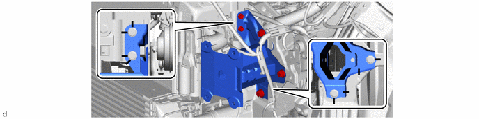
| (c) Tighten the 5 bolts. Torque: Bolt A : 40 N·m {408 kgf·cm, 30 ft·lbf} Bolt B : 7.1 N·m {72 kgf·cm, 63 in·lbf} |
|
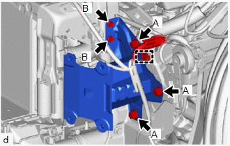
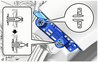
(d) Engage the clamp.
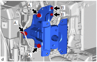
4. INSTALL FRONT SIDE MEMBER BRACKET SUB-ASSEMBLY RH
(a) If install a new front side member bracket sub-assembly RH:
(1) Temporarily install the front side member bracket sub-assembly RH with the 5 bolts until the "reference value" and " point-to-point distance" are aligned.
- Vehicle Exterior > BODY PANEL > RADIATOR SUPPORT > REFERENCE VALUE
- Vehicle Exterior > BODY DIMENSIONS > ENGINE COMPARTMENT REFERENCE VALUES > POINT-TO-POINT DISTANCE
(b) If reusing the front side member bracket sub-assembly RH:
(1) Temporarily install the front side member bracket sub-assembly RH with the 5 bolts until the matchmarks are aligned.
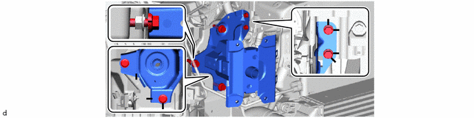
| (c) Tighten the 5 bolts. Torque: Bolt A : 40 N·m {408 kgf·cm, 30 ft·lbf} Bolt B : 7.1 N·m {72 kgf·cm, 63 in·lbf} |
|
5. INSTALL NO. 1 RADIATOR AIR GUIDE LH
(a) Engage the guide and claw to install the No. 1 radiator air guide LH as shown in the illustration.
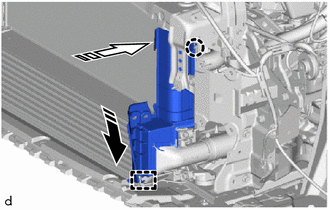
.png) | Install in this Direction (1) |
.png) | Install in this Direction (2) |
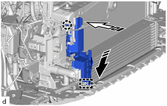
6. INSTALL NO. 1 RADIATOR AIR GUIDE RH
(a) Engage the guide and claw to install the No. 1 radiator air guide RH as shown in the illustration.
|
| Install in this Direction (1) |
|
| Install in this Direction (2) |
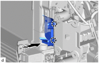
7. INSTALL FRONT RADIATOR SIDE AIR GUIDE PLATE LH
(a) Engage the claws to install the front radiator side air guide plate LH as shown in the illustration.
|
| Install in this Direction |
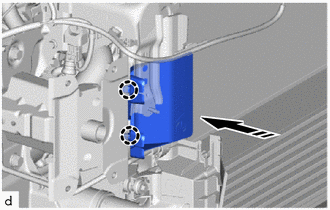
8. INSTALL FRONT RADIATOR SIDE AIR GUIDE PLATE RH
(a) Engage the claws to install the front radiator side air guide plate RH as shown in the illustration.
|
| Install in this Direction |
9. INSTALL FRONT BUMPER REINFORCEMENT
| (a) Engage the guides to install the front bumper reinforcement. |
|
.png)
(b) Install the 8 bolts.
Torque:
67 N·m {683 kgf·cm, 49 ft·lbf}
| (c) Engage the clamp to install the wire harness. |
|
.png)
10. INSTALL COOL AIR INTAKE DUCT
| (a) Install the cool air intake duct with the 3 clips. |
|
.png)
11. INSTALL THERMISTOR ASSEMBLY
| (a) Engage the clamps to install the thermistor assembly. |
|
.png)
12. INSTALL FRONT BUMPER ENERGY ABSORBER
| (a) Engage the guides to install the front bumper energy absorber. |
|
.png)
13. INSTALL RADIATOR UPPER AIR GUIDE PLATE
| (a) Install the radiator upper air guide plate with the 2 clips. |
|
.png)
14. INSTALL FRONT BUMPER SIDE RETAINER LH
| (a) Engage the claw and clip to install the front bumper side retainer LH as shown in the illustration. |
|
15. INSTALL FRONT BUMPER SIDE RETAINER RH
HINT:
Use the same procedure as for the LH side.
16. INSTALL HEADLIGHT ASSEMBLY LH
Click here
17. INSTALL HEADLIGHT ASSEMBLY RH
HINT:
Use the same procedure as for the LH side.
18. INSTALL RADIATOR GRILLE EMBLEM ASSEMBLY
| (a) Engage the claws to install the radiator grille emblem assembly. |
|
.png)
(b) Install the screw.
19. INSTALL RADIATOR GRILLE SIDE MOULDING LH
| (a) Engage the claws to install the radiator grille side moulding LH. |
|
.png)
(b) Install the screw.
20. INSTALL RADIATOR GRILLE SIDE MOULDING RH
HINT:
Use the same procedure as for the LH side.
21. INSTALL LOWER RADIATOR GRILLE SUB-ASSEMBLY
| (a) Engage the claws to install the lower radiator grille sub-assembly. |
|
.png)
(b) Install the 4 clips and 3 screws.
22. INSTALL FRONT BUMPER EXTENSION MOUNTING BRACKET
| (a) Engage the guides and claws to install the front bumper extension mounting bracket. |
|
.png)
(b) Install the 2 screws.
23. INSTALL HOOD TO FRONT END PANEL SEAL
| (a) Engage the clips to install the hood to front end panel seal. |
|
.png)
24. INSTALL FRONT BUMPER HOLE COVER
| (a) Engage the hook and claws to install the front bumper hole cover. |
|
.png)
25. INSTALL FOG LIGHT COVER LH
| (a) Engage the guide and claws to install the fog light cover LH. |
|
.png)
(b) Install the 2 screws.
26. INSTALL FOG LIGHT COVER RH
HINT:
Use the same procedure as for the LH side.
27. INSTALL FOG LIGHT ASSEMBLY LH
Click here
28. INSTALL FOG LIGHT ASSEMBLY RH
HINT:
Use the same procedure as for the LH side.
29. INSTALL NO. 3 ENGINE ROOM WIRE (w/ Pre-collision System)
(a) Engage the clamps to install the No. 3 engine room wire.
.png)
30. INSTALL MILLIMETER WAVE RADAR SENSOR ASSEMBLY (w/ Pre-collision System)
Click here
 Disassembly
DISASSEMBLY PROCEDURE 1. REMOVE MILLIMETER WAVE RADAR SENSOR ASSEMBLY (w/ Pre-collision System) Click here
2. REMOVE NO. 3 ENGINE ROOM WIRE (w/ Pre-collision System) (a) Disengage the clamps to remove the No...
 Installation
INSTALLATION PROCEDURE 1. INSTALL FRONT BUMPER ASSEMBLY (a) Install the 3 grommets. HINT: Use the same procedure for the RH side and LH side. (b) Temporarily install the front bumper assembly with the 2 clips and 2 bolts...
Other information:
Toyota Yaris XP210 (2020-2026) Reapir and Service Manual: Removal
REMOVAL PROCEDURE 1. SEPARATE ENGINE WIRE (a) Remove the bolt and engine wire. 2. REMOVE IGNITION COIL ASSEMBLY (a) Disconnect the ignition coil assembly connector. (b) Remove the bolt and ignition coil assembly. 3. REMOVE CAMSHAFT POSITION SENSOR (for Intake Side) (a) Disconnect the camshaft position sensor connector...
Toyota Yaris XP210 (2020-2026) Reapir and Service Manual: Taillight Relay Circuit
DESCRIPTION The main body ECU (multiplex network body ECU) controls the, taillight and license plate light. WIRING DIAGRAM CAUTION / NOTICE / HINT NOTICE: First perform the communication function inspections in How to Proceed with Troubleshooting to confirm that there are no CAN communication malfunctions before troubleshooting this symptom...
Categories
- Manuals Home
- Toyota Yaris Owners Manual
- Toyota Yaris Service Manual
- Headlights
- Brake System Control Module "A" System Voltage System Voltage Low (C137BA2)
- Auto Lock/Unlock Function
- New on site
- Most important about car
Key Suspend Function
If a key is left in the vehicle, the functions of the key left in the vehicle are temporarily suspended to prevent theft of the vehicle.
To restore the functions, press the unlock button on the functions-suspended key in the vehicle.