Toyota Yaris: Can Communication System / Power Steering ECU Communication Stop Mode
DESCRIPTION
| Detection Item | Symptom | Trouble Area |
|---|---|---|
| Power Steering ECU Communication Stop Mode | Communication stop for "Power Steering (EPS)" is indicated on the "Communication Bus Check" screen of the GTS. Click here
|
|

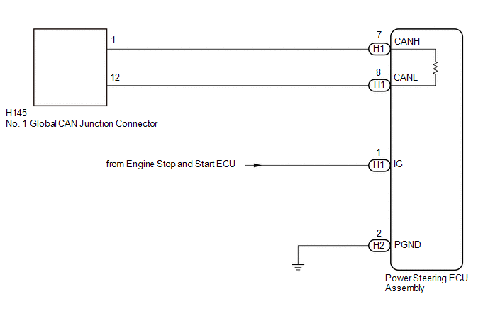
WIRING DIAGRAM
CAUTION / NOTICE / HINT
CAUTION:
When performing the confirmation driving pattern, obey all speed limits and traffic laws.
NOTICE:
-
Because the order of diagnosis is important to allow correct diagnosis, make sure to begin troubleshooting using How to Proceed with Troubleshooting when CAN communication system related DTCs are output.
Click here

- Before measuring the resistance of the CAN bus, turn the ignition switch off and leave the vehicle for 1 minute or more without operating the key or any switches, or opening or closing the doors. After that, disconnect the cable from the negative (-) auxiliary battery terminal and leave the vehicle for 1 minute or more before measuring the resistance.
-
After the ignition switch is turned off, there may be a waiting time before disconnecting the negative (-) auxiliary battery terminal.
Click here

-
When disconnecting and reconnecting the auxiliary battery, there is an automatic learning function that completes learning when the respective system is used.
Click here

-
Some parts must be initialized and set when replacing or removing and installing parts.
Click here

-
After performing repairs, perform the DTC check procedure and confirm that the DTCs are not output again.
DTC check procedure: Turn the ignition switch to ON and wait for 1 minute or more. Then operate the suspected malfunctioning system and drive the vehicle at 60 km/h (37 mph) or more for 5 minutes or more.
-
After the repair, perform the CAN bus check and check that all the ECUs and sensors connected to the CAN communication system are displayed as normal.
Click here

HINT:
- Before disconnecting related connectors for inspection, push in on each connector body to check that the connector is not loose or disconnected.
- When a connector is disconnected, check that the terminals and connector body are not cracked, deformed or corroded.
PROCEDURE
| 1. | CHECK FOR OPEN IN CAN BUS LINES (POWER STEERING ECU ASSEMBLY MAIN LINE) |
(a) Disconnect the cable from the negative (-) auxiliary battery terminal.
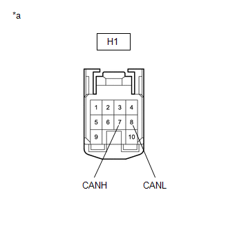
(b) Disconnect the power steering ECU assembly connector.
| (c) Measure the resistance according to the value(s) in the table below. Standard Resistance:
|
|
| NG |
 | REPAIR OR REPLACE CAN MAIN BUS LINES OR CONNECTOR (POWER STEERING ECU ASSEMBLY) |
|

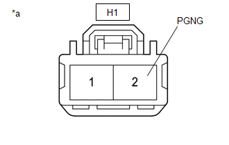
| 2. | CHECK HARNESS AND CONNECTOR (POWER SOURCE CIRCUIT) |
| (a) Measure the resistance according to the value(s) in the table below. Standard Resistance:
|
|
| NG |
 | REPAIR OR REPLACE HARNESS OR CONNECTOR (POWER SOURCE CIRCUIT) |
|

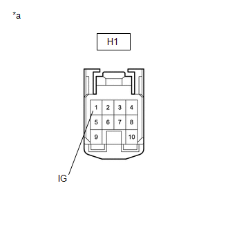
| 3. | CHECK HARNESS AND CONNECTOR (POWER SOURCE CIRCUIT) |
(a) Reconnect the cable to the negative (-) auxiliary battery terminal.
| (b) Measure the voltage according to the value(s) in the table below. Standard Voltage:
|
|
| OK |
 | REPLACE POWER STEERING ECU ASSEMBLY |
| NG |
 | GO TO STOP AND START SYSTEM (BACKUP BOOST CONVERTER CIRCUIT) |
 Air Conditioning Amplifier Communication Stop Mode
DESCRIPTION Detection Item Symptom Trouble Area Air Conditioning Amplifier Communication Stop Mode Communication stop for "Air Conditioning Amplifier" is indicated on the "Communication Bus Check" screen of the GTS...
 Steering Angle Sensor Communication Stop Mode
DESCRIPTION Detection Item Symptom Trouble Area Steering Angle Sensor Communication Stop Mode Communication stop for "Spiral cable (Steering Angle Sensor)" is indicated on the "Communication Bus Check" screen of the GTS...
Other information:
Toyota Yaris XP210 (2020-2026) Reapir and Service Manual: Lost Communication with Steering Angle Sensor Module Missing Message (U012687,U010087,U012987,U014087,U023A87)
DESCRIPTION The power steering ECU assembly receives signals from the steering sensor, skid control ECU (brake actuator assembly), forward recognition camera, ECM and clearance warning ECU assembly via CAN communication. DTC No. Detection Item DTC Detection Condition Trouble Area Warning Indicate Return-to-normal Condition Note U010087 Lost Communication With ECM/PCM "A" Missing Message Lost communication with ECM CAN communication system ECM EPS warning light: Does not come on After normal confirmation - U012687 Lost Communication with Steering Angle Sensor Module Missing Message Lost communication with steering sensor CAN communication system Steering sensor EPS warning light: Does not come on After normal confirmation - U012987 Lost Communication with Brake System Control Module Missing Message Lost communication with skid control ECU (brake booster with master cylinder assembly) CAN communication system Skid control ECU (Brake booster with master cylinder assembly)(for TMC Made HV Model) Skid control ECU (Brake actuator assembly)(for TMMF Made HV Model) EPS warning light: Does not come on After normal confirmation - U014087 Lost Communication with Body Control Module Missing Message Lost communication with main body ECU (multiplex network body ECU) CAN communication system Main body ECU (multiplex network body ECU) EPS warning light: Does not come on After normal confirmation - U023A87 Lost Communication with Image Processing Module "A" Missing Message Lost communication with forward recognition camera CAN communication system Forward recognition camera EPS warning light: Does not come on After normal confirmation w/ Toyota Safety Sense PROCEDURE 1...
Toyota Yaris XP210 (2020-2026) Reapir and Service Manual: Cooling Fan Circuit
DESCRIPTION The ECM calculates an appropriate cooling fan speed based on the engine coolant temperature, air conditioning switch status, refrigerant pressure, engine speed and vehicle speed, and sends a signal to the cooling fan ECU (fan with motor assembly)...
Categories
- Manuals Home
- Toyota Yaris Owners Manual
- Toyota Yaris Service Manual
- Fuel Gauge
- Adjustment
- To Set Speed
- New on site
- Most important about car
Refueling
Before refueling, close all the doors, windows, and the liftgate/trunk lid, and switch the ignition OFF.
To open the fuel-filler lid, pull the remote fuel-filler lid release.
