Toyota Yaris: Can Communication System / Air Conditioning Amplifier Communication Stop Mode
DESCRIPTION
| Detection Item | Symptom | Trouble Area |
|---|---|---|
| Air Conditioning Amplifier Communication Stop Mode | Communication stop for "Air Conditioning Amplifier" is indicated on the "Communication Bus Check" screen of the GTS. Click here
|
|

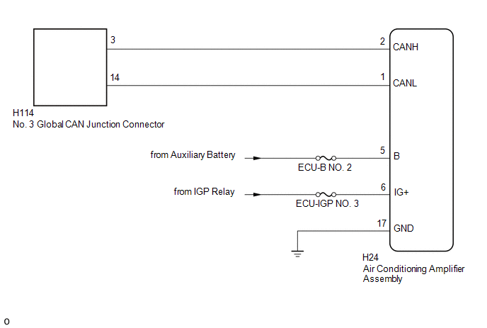
WIRING DIAGRAM
CAUTION / NOTICE / HINT
CAUTION:
When performing the confirmation driving pattern, obey all speed limits and traffic laws.
NOTICE:
-
Because the order of diagnosis is important to allow correct diagnosis, make sure to begin troubleshooting using How to Proceed with Troubleshooting when CAN communication system related DTCs are output.
Click here

- Before measuring the resistance of the CAN bus, turn the ignition switch off and leave the vehicle for 1 minute or more without operating the key or any switches, or opening or closing the doors. After that, disconnect the cable from the negative (-) auxiliary battery terminal and leave the vehicle for 1 minute or more before measuring the resistance.
-
After the ignition switch is turned off, there may be a waiting time before disconnecting the negative (-) auxiliary battery terminal.
Click here

-
When disconnecting and reconnecting the auxiliary battery, there is an automatic learning function that completes learning when the respective system is used.
Click here

-
Some parts must be initialized and set when replacing or removing and installing parts.
Click here

-
After performing repairs, perform the DTC check procedure and confirm that the DTCs are not output again.
DTC check procedure: Turn the ignition switch to ON and wait for 1 minute or more. Then operate the suspected malfunctioning system and drive the vehicle at 60 km/h (37 mph) or more for 5 minutes or more.
-
After the repair, perform the CAN bus check and check that all the ECUs and sensors connected to the CAN communication system are displayed as normal.
Click here

- Inspect the fuses for circuits related to this system before performing the following procedure.
HINT:
- Before disconnecting related connectors for inspection, push in on each connector body to check that the connector is not loose or disconnected.
- When a connector is disconnected, check that the terminals and connector body are not cracked, deformed or corroded.
PROCEDURE
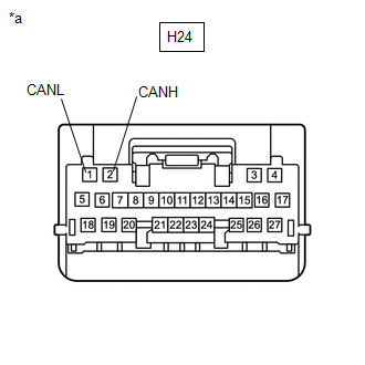
| 1. | CHECK FOR OPEN IN CAN BUS LINES (AIR CONDITIONING AMPLIFIER ASSEMBLY BRANCH LINE) |
(a) Disconnect the cable from the negative (-) auxiliary battery terminal.
(b) Disconnect the air conditioning amplifier assembly connector.
| (c) Measure the resistance according to the value(s) in the table below. Standard Resistance:
|
|
| NG |
 | REPAIR OR REPLACE CAN BRANCH LINES OR CONNECTOR (AIR CONDITIONING AMPLIFIER ASSEMBLY) |
|

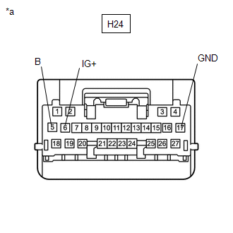
| 2. | CHECK HARNESS AND CONNECTOR (POWER SOURCE CIRCUIT) |
| (a) Measure the resistance according to the value(s) in the table below. Standard Resistance:
|
|
(b) Reconnect the cable to the negative (-) auxiliary battery terminal.
(c) Measure the voltage according to the value(s) in the table below.
Standard Voltage:
| Tester Connection | Condition | Specified Condition |
|---|---|---|
| H24-5 (B) - Body ground | Ignition switch off | 11 to 14 V |
| H24-6 (IG+) - Body ground | Ignition switch ON | 11 to 14 V |
| OK |
 | REPLACE AIR CONDITIONING AMPLIFIER ASSEMBLY |
| NG |
 | REPAIR OR REPLACE HARNESS OR CONNECTOR (POWER SOURCE CIRCUIT) |
 Skid Control ECU Communication Stop Mode
DESCRIPTION Detection Item Symptom Trouble Area Skid Control ECU Communication Stop Mode Communication stop for "Skid Control (ABS/VSC/TRAC)" is indicated on the "Communication Bus Check" screen of the GTS...
 Power Steering ECU Communication Stop Mode
DESCRIPTION Detection Item Symptom Trouble Area Power Steering ECU Communication Stop Mode Communication stop for "Power Steering (EPS)" is indicated on the "Communication Bus Check" screen of the GTS...
Other information:
Toyota Yaris XP210 (2020-2026) Reapir and Service Manual: Camera Heater
ComponentsCOMPONENTS ILLUSTRATION *1 FORWARD RECOGNITION WITH HEATER HOOD SUB-ASSEMBLY - - RemovalREMOVAL PROCEDURE 1. REMOVE FORWARD RECOGNITION CAMERA Click here 2. REMOVE FORWARD RECOGNITION WITH HEATER HOOD SUB-ASSEMBLY NOTICE: Do not touch the inner surface of the forward recognition with heater hood sub-assembly...
Toyota Yaris XP210 (2020-2026) Reapir and Service Manual: Dtc Check / Clear
DTC CHECK / CLEAR CHECK FOR DTC (CHECK USING GTS) (a) Enter the following menus: Body Electrical / Active Noise Control / Trouble Codes. Body Electrical > Active Noise Control > Trouble Codes (b) Check the details of the DTC(s). Click here CLEAR DTC (CLEAR USING GTS) (a) Enter the following menus: Body Electrical / Active Noise Control / Trouble Codes...
Categories
- Manuals Home
- Toyota Yaris Owners Manual
- Toyota Yaris Service Manual
- Removal
- Opening and Closing the Liftgate/Trunk Lid
- Fuel Gauge
- New on site
- Most important about car
Liftgate/Trunk Lid
WARNING
Never allow a person to ride in the luggage compartment/trunk
Allowing a person to ride in the luggage compartment/trunk is dangerous. The person in the luggage compartment/trunk could be seriously injured or killed during sudden braking or a collision.
Do not drive with the liftgate/trunk lid open