Toyota Yaris: Can Communication System / Skid Control ECU Communication Stop Mode
DESCRIPTION
| Detection Item | Symptom | Trouble Area |
|---|---|---|
| Skid Control ECU Communication Stop Mode | Communication stop for "Skid Control (ABS/VSC/TRAC)" is indicated on the "Communication Bus Check" screen of the GTS. Click here
|
|

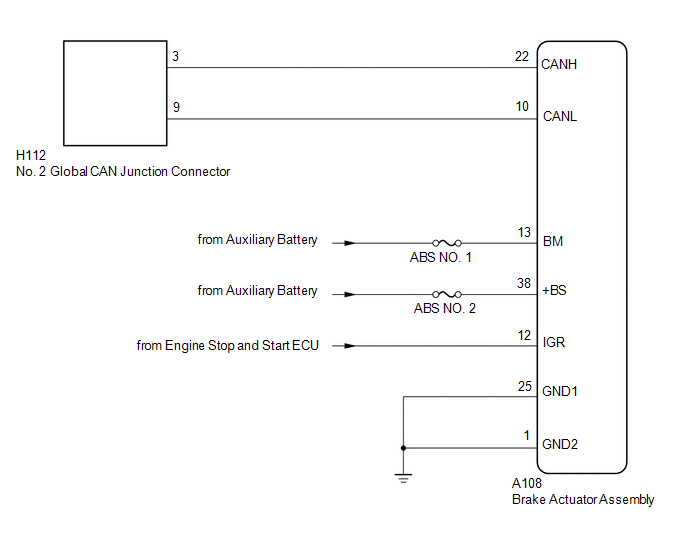
WIRING DIAGRAM
CAUTION / NOTICE / HINT
CAUTION:
When performing the confirmation driving pattern, obey all speed limits and traffic laws.
NOTICE:
-
Because the order of diagnosis is important to allow correct diagnosis, make sure to begin troubleshooting using How to Proceed with Troubleshooting when CAN communication system related DTCs are output.
Click here

- Before measuring the resistance of the CAN bus, turn the ignition switch off and leave the vehicle for 1 minute or more without operating the key or any switches, or opening or closing the doors. After that, disconnect the cable from the negative (-) auxiliary battery terminal and leave the vehicle for 1 minute or more before measuring the resistance.
-
After the ignition switch is turned off, there may be a waiting time before disconnecting the negative (-) auxiliary battery terminal.
Click here

-
When disconnecting and reconnecting the auxiliary battery, there is an automatic learning function that completes learning when the respective system is used.
Click here

-
Some parts must be initialized and set when replacing or removing and installing parts.
Click here

-
After performing repairs, perform the DTC check procedure and confirm that the DTCs are not output again.
DTC check procedure: Turn the ignition switch to ON and wait for 1 minute or more. Then operate the suspected malfunctioning system and drive the vehicle at 60 km/h (37 mph) or more for 5 minutes or more.
-
After the repair, perform the CAN bus check and check that all the ECUs and sensors connected to the CAN communication system are displayed as normal.
Click here

- Inspect the fuses for circuits related to this system before performing the following procedure.
HINT:
- Before disconnecting related connectors for inspection, push in on each connector body to check that the connector is not loose or disconnected.
- When a connector is disconnected, check that the terminals and connector body are not cracked, deformed or corroded.
PROCEDURE
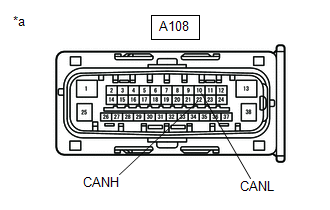
| 1. | CHECK FOR OPEN IN CAN BUS LINES (BRAKE ACTUATOR ASSEMBLY BRANCH LINE) |
(a) Disconnect the cable from the negative (-) auxiliary battery terminal.
(b) Disconnect the brake actuator assembly connector.
| (c) Measure the resistance according to the value(s) in the table below. Standard Resistance:
|
|
| NG |
 | REPAIR OR REPLACE CAN BRANCH LINES OR CONNECTOR (BRAKE ACTUATOR ASSEMBLY) |
|

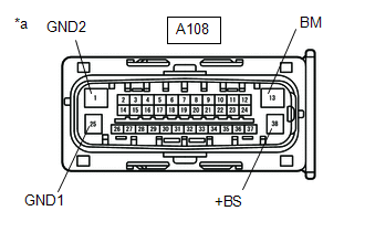
| 2. | CHECK HARNESS AND CONNECTOR (POWER SOURCE CIRCUIT) |
| (a) Measure the resistance according to the value(s) in the table below. Standard Resistance:
|
|
(b) Reconnect the cable to the negative (-) auxiliary battery terminal.
(c) Measure the voltage according to the value(s) in the table below.
Standard Voltage:
| Tester Connection | Condition | Specified Condition |
|---|---|---|
| A108-13 (BM) - Body ground | Ignition switch off | 11 to 14 V |
| A108-38 (+BS) - Body ground | Ignition switch off | 11 to 14 V |
| NG |
 | REPAIR OR REPLACE HARNESS OR CONNECTOR (POWER SOURCE CIRCUIT) |
|

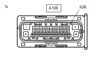
| 3. | CHECK HARNESS AND CONNECTOR (POWER SOURCE CIRCUIT) |
| (a) Measure the voltage according to the value(s) in the table below. Standard Voltage:
|
|
| OK |
 | REPLACE BRAKE ACTUATOR ASSEMBLY |
| NG |
 | GO TO STOP AND START SYSTEM (BACKUP BOOST CONVERTER CIRCUIT) |
 Check CAN Communication Connection
DESCRIPTION Symptom Trouble Area Check CAN Communication Connection
CAN main bus line, CAN branch line or connector
Power source circuit of central gateway ECU (network gateway ECU)
Central gateway ECU (network gateway ECU) ground circuit
Central gateway ECU (network gateway ECU)
Power source circuit of DLC3
DLC3 ground circuit
WIRING DIAGRAM
CAUTION / NOTICE / HINT CAUTION: When performing the confirmation driving pattern, obey all speed limits and traffic laws...
 Air Conditioning Amplifier Communication Stop Mode
DESCRIPTION Detection Item Symptom Trouble Area Air Conditioning Amplifier Communication Stop Mode Communication stop for "Air Conditioning Amplifier" is indicated on the "Communication Bus Check" screen of the GTS...
Other information:
Toyota Yaris XP210 (2020-2026) Reapir and Service Manual: Clearance Light/Daytime Running Light Circuit
DESCRIPTION Clearance light function: When the main body ECU (multiplex network body ECU) receives the light control switch position signal, it sends an illumination request signal to the light control LED ECU and illuminates the clearance lights. Daytime running light function: When the operation conditions of the daytime running lights are met, the main body ECU (multiplex network body ECU) sends an illumination request signal to the light control LED ECU and illuminates the daytime running lights...
Toyota Yaris XP210 (2020-2026) Owner's Manual: To Turn Off an Armed System
An armed system can be turned off using any one of the following methods: Pressing the unlock button on the smart key. Starting the engine with the push button start. With the advanced keyless function:Pressing a request switch on the doors...
Categories
- Manuals Home
- Toyota Yaris Owners Manual
- Toyota Yaris Service Manual
- Adjustment
- Fuel Gauge
- Power Integration No.1 System Missing Message (B235287,B235587,B235787-B235987)
- New on site
- Most important about car
Keys

To use the auxiliary key, press the knob and pull out the auxiliary key from the smart key.
