Toyota Yaris: Can Communication System / Check CAN Communication Connection
DESCRIPTION
| Symptom | Trouble Area |
|---|---|
| Check CAN Communication Connection |
|
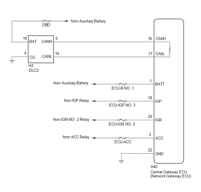
WIRING DIAGRAM
CAUTION / NOTICE / HINT
CAUTION:
When performing the confirmation driving pattern, obey all speed limits and traffic laws.
NOTICE:
-
Because the order of diagnosis is important to allow correct diagnosis, make sure to begin troubleshooting using How to Proceed with Troubleshooting when CAN communication system related DTCs are output.
Click here

- Before measuring the resistance of the CAN bus, turn the ignition switch off and leave the vehicle for 1 minute or more without operating the key or any switches, or opening or closing the doors. After that, disconnect the cable from the negative (-) auxiliary battery terminal and leave the vehicle for 1 minute or more before measuring the resistance.
-
After the ignition switch is turned off, there may be a waiting time before disconnecting the negative (-) auxiliary battery terminal.
Click here

-
When disconnecting and reconnecting the auxiliary battery, there is an automatic learning function that completes learning when the respective system is used.
Click here

-
Some parts must be initialized and set when replacing or removing and installing parts.
Click here

-
After performing repairs, perform the DTC check procedure and confirm that the DTCs are not output again.
DTC check procedure: Turn the ignition switch to ON and wait for 1 minute or more. Then operate the suspected malfunctioning system and drive the vehicle at 60 km/h (37 mph) or more for 5 minutes or more.
-
After the repair, perform the CAN bus check and check that all the ECUs and sensors connected to the CAN communication system are displayed as normal.
Click here

- Inspect the fuses for circuits related to this system before performing the following procedure.
HINT:
- Before disconnecting related connectors for inspection, push in on each connector body to check that the connector is not loose or disconnected.
- When a connector is disconnected, check that the terminals and connector body are not cracked, deformed or corroded.
PROCEDURE
| 1. | CHECK GTS OPERATION |
HINT:
Read the GTS operator's manual before use.
Click here

(a) Connect the GTS to the DLC3 of another vehicle.
(b) Turn the ignition switch to ON.
(c) Turn the GTS on.
(d) Check that the GTS and ECUs can communicate with the ignition switch ON.
HINT:
- ECUs and sensors are not displayed on the "Communication Bus Check" screen when the GTS cannot communicate with the vehicle.
- If communication between the GTS and ECUs is not possible, either the GTS or vehicle has a malfunction.
- If communication between the GTS and ECUs is still not possible even when the GTS is connected to another vehicle, the GTS has a malfunction. Perform the self tests described in the GTS operator's manual. (The GTS may be malfunctioning or its auxiliary battery may be discharged.)
| Result | Proceed to |
|---|---|
| OK (Communication between the GTS and the vehicle is not possible, but communication is possible when connected to another vehicle.) | A |
| NG (Communication is not possible between the GTS and the vehicle, nor between the GTS and another vehicle.) | B |
| B |
 | REFER TO GTS OPERATOR'S MANUAL |
|

| 2. | CHECK HARNESS AND CONNECTOR (DLC3 POWER SOURCE CIRCUIT) |
| (a) Measure the voltage according to the value(s) in the table below. Standard Voltage:
|
|
(b) Disconnect the cable from the negative (-) auxiliary battery terminal.
(c) Measure the resistance according to the value(s) in the table below.
Standard Resistance:
| Tester Connection | Condition | Specified Condition |
|---|---|---|
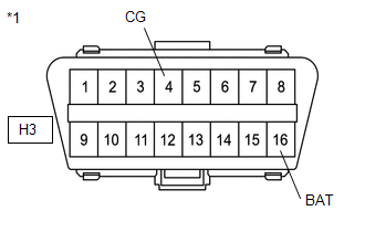
| H3-4 (CG) - Body ground | Cable disconnected from negative (-) auxiliary battery terminal | Below 1 Ω |
| NG |
 | REPAIR OR REPLACE HARNESS OR CONNECTOR (DLC3 POWER SOURCE CIRCUIT) |
|

| 3. | CHECK OPEN IN CAN BUS LINES |
| (a) Measure the resistance according to the value(s) in the table below. Standard Resistance:
|
|
| NG |
 | GO TO STEP 6 |
|

| 4. | CHECK SHORT IN CAN BUS LINE |
| (a) Measure the resistance according to the value(s) in the table below. Standard Resistance:
|
|
| NG |
 | GO TO STEP 7 |
|

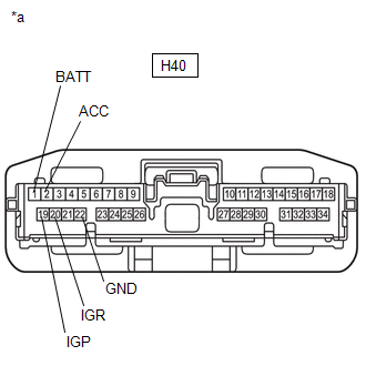
| 5. | CHECK HARNESS AND CONNECTOR (POWER SOURCE CIRCUIT) |
(a) Disconnect the central gateway ECU (network gateway ECU) connector.
| (b) Measure the resistance according to the value(s) in the table below. Standard Resistance:
|
|
(c) Reconnect the cable to the negative (-) auxiliary battery terminal.
(d) Measure the voltage according to the value(s) in the table below.
Standard Voltage:
| Tester Connection | Condition | Specified Condition |
|---|---|---|
| H40-1 (BAT) - Body ground | Ignition switch off | 11 to 14 V |
| H40-2 (ACC) - Body ground | Ignition switch ACC | 11 to 14 V |
| H40-20 (IGR) - Body ground | Ignition switch ON | 11 to 14 V |
| H40-19 (IGP) - Body ground | Ignition switch ON | 11 to 14 V |
| OK |
 | REPLACE CENTRAL GATEWAY ECU (NETWORK GATEWAY ECU) |
| NG |
 | REPAIR OR REPLACE HARNESS OR CONNECTOR (POWER SOURCE CIRCUIT) |
| 6. | CHECK FOR OPEN IN CAN BUS LINE (CENTRAL GATEWAY ECU (NETWORK GATEWAY ECU) - DLC3) |
(a) Disconnect the central gateway ECU (network gateway ECU) connector.
(b) Measure the resistance according to the value(s) in the table below.
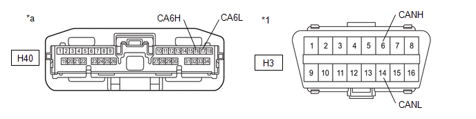
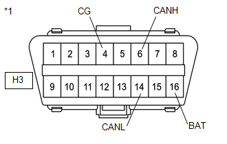
| *1 | DLC3 | - | - |
| *a | Front view of wire harness connector (to Central Gateway ECU (Network Gateway ECU)) | - | - |
Standard Resistance:
| Tester Connection | Condition | Specified Condition |
|---|---|---|
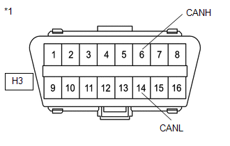
| H40-16 (CA6H) - H3-6 (CANH) | Cable disconnected from negative (-) auxiliary battery terminal | Below 1 Ω |
| H40-17 (CA6L) - H3-14 (CANL) |
| OK |
 | REPLACE CENTRAL GATEWAY ECU (NETWORK GATEWAY ECU) |
| NG |
 | REPAIR OR REPLACE HARNESS OR CONNECTOR (CENTRAL GATEWAY ECU (NETWORK GATEWAY ECU) - DLC3) |
| 7. | CHECK SHORT IN CAN BUS LINE |
(a) Disconnect the H40 central gateway ECU (network gateway ECU) connector.
| (b) Measure the resistance according to the value(s) in the table below. Standard Resistance:
|
|

| OK |
 | REPLACE CENTRAL GATEWAY ECU (NETWORK GATEWAY ECU) |
| NG |
 | REPAIR OR REPLACE HARNESS OR CONNECTOR (DLC3 - CENTRAL GATEWAY ECU (NETWORK GATEWAY ECU)) |
 Lost Communication With Brake System Control Module(ch2) Missing Message (U117087)
DESCRIPTION The brake actuator assembly communicates with the ECM and engine stop and start ECU. When the brake actuator assembly does not receive data from the engine stop and start ECU, the engine stop and start ECU stores DTC U117087...
 Skid Control ECU Communication Stop Mode
DESCRIPTION Detection Item Symptom Trouble Area Skid Control ECU Communication Stop Mode Communication stop for "Skid Control (ABS/VSC/TRAC)" is indicated on the "Communication Bus Check" screen of the GTS...
Other information:
Toyota Yaris XP210 (2020-2026) Reapir and Service Manual: Components
C..
Toyota Yaris XP210 (2020-2026) Reapir and Service Manual: Tongue Plate Stopper
ComponentsCOMPONENTS ILLUSTRATION *1 TONGUE PLATE STOPPER - - ● Non-reusable part - - ReplacementREPLACEMENT PROCEDURE 1. REMOVE TONGUE PLATE STOPPER (a) Slide the tongue plate above the installation position of the tongue plate stopper, and temporarily hold it with adhesive tape...
Categories
- Manuals Home
- Toyota Yaris Owners Manual
- Toyota Yaris Service Manual
- G16e-gts (engine Mechanical)
- Immobilizer System
- Brake System Control Module "A" System Voltage System Voltage Low (C137BA2)
- New on site
- Most important about car
Front Seat Belt Pretensioners
The front seat belt pretensioners are designed to deploy in moderate or severe frontal, near frontal collisions.
In addition, the pretensioners operate when a side collision or a rollover accident is detected. The pretensioners operate differently depending on what types of air bags are equipped. For more details about the seat belt pretensioner operation, refer to the SRS Air Bag Deployment Criteria.