Toyota Yaris: Brake Booster / Removal
REMOVAL
CAUTION / NOTICE / HINT
The necessary procedures (adjustment, calibration, initialization or registration) that must be performed after parts are removed and installed, or replaced during brake booster assembly removal/installation are shown below.
HINT:
When the cable is disconnected / reconnected to the auxiliary battery terminal, systems temporarily stop operating. However, each system has a function that completes learning the first time the system is used.
-
Learning completes when vehicle is driven
Effect/Inoperative Function When Necessary Procedures are not Performed
Necessary Procedures
Link
Lane tracing assist system
Drive the vehicle straight ahead at 35 km/h (22 mph) or more for 5 second or more.

Pre-collision system
Parking support brake system
Stop and start system
Drive the vehicle until stop and start control is permitted (approximately 5 to 60 minutes)

-
Learning completes when vehicle is operated normally
Effect/Inoperative Function When Necessary Procedures are not Performed
Necessary Procedures
Link
Power door lock control system
- Back door opener
Perform door unlock operation with door control switch or electrical key transmitter sub-assembly switch.

Air conditioning system
After the ignition switch is turned to ON, the servo motor standard position is recognized.
-
PROCEDURE
1. REMOVE BRAKE MASTER CYLINDER SUB-ASSEMBLY
Click here

2. REMOVE NO. 1 ENGINE UNDER COVER ASSEMBLY
Click here

3. REMOVE DASH PANEL HEAT INSULATOR
| (a) Remove the nut. |
|
| (b) Remove the nut, clamp and dash panel heat insulator. |
|
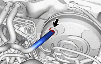
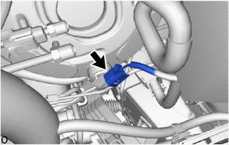
4. DISCONNECT VACUUM HOSE ASSEMBLY
| (a) Slide the clip and disconnect the vacuum hose assembly from the brake booster assembly. |
|
5. REMOVE NO. 1 INSTRUMENT PANEL UNDER COVER SUB-ASSEMBLY
Click here

6. REMOVE COLUMN HOLE COVER SILENCER SHEET
Click here

7. DISCONNECT NO. 2 STEERING INTERMEDIATE SHAFT ASSEMBLY
Click here

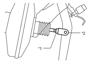
8. LOOSEN CLEVIS LOCK NUT
| (a) Loosen the lock nut of the brake master cylinder push rod clevis. |
|
9. REMOVE BRAKE PEDAL RETURN SPRING
Click here

10. REMOVE PUSH ROD PIN
Click here

11. REMOVE BRAKE BOOSTER ASSEMBLY
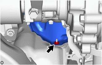
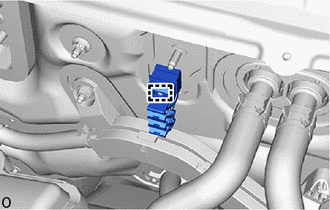
| (a) Remove the bolt to separate the engine room main wire. |
|
(b) Disengage the clamp.
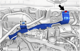
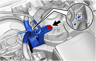
| (c) Disconnect the vacuum sensor connector. |
|
(d) Apply protective tape to the vehicle body as shown in the illustration.
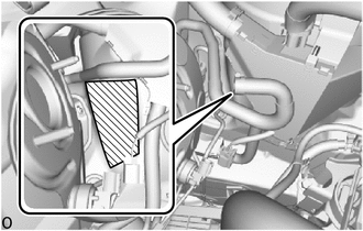
 | Protective Tape |
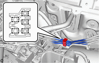
| (e) Disengage the 5 clamps to separate the brake lines from the No. 2 brake tube clamp. |
|
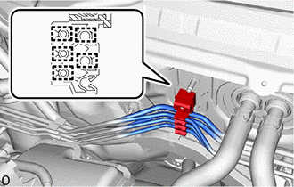
| (f) Disengage the clamp and remove the No. 2 brake tube clamp from the vehicle body. |
|
| (g) Disengage the 5 clamps to remove the No. 1 brake tube clamp from the brake lines. |
|
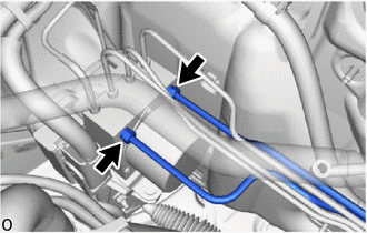
| (h) Using a union nut wrench, disconnect the 2 brake lines from the brake actuator assembly. |
|
| (i) Remove the 4 nuts. |
|
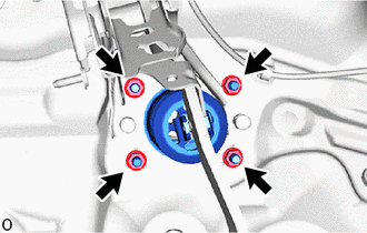
(j) Remove the brake master cylinder push rod clevis and lock nut from the brake booster assembly.
(k) Remove the brake booster assembly from the vehicle body.
NOTICE:
Do not apply excessive force to the brake lines.
12. REMOVE BRAKE BOOSTER GASKET
(a) Remove the brake booster gasket from the brake booster assembly.
 Disassembly
DISASSEMBLY PROCEDURE 1. REMOVE BRAKE VACUUM CHECK VALVE ASSEMBLY (a) Remove the brake vacuum check valve assembly from the brake booster assembly. (b) Remove the check valve grommet from the brake booster assembly...
 Inspection
INSPECTION PROCEDURE 1. INSPECT BRAKE VACUUM CHECK VALVE ASSEMBLY (a) Check that there is ventilation from the booster side to the engine side, and no ventilation from the engine side to the booster side of the brake vacuum check valve assembly...
Other information:
Toyota Yaris XP210 (2020-2026) Owner's Manual: Rear Coat Hooks
Always hang clothes on the coat hooks and the assist grips without hangers. WARNING Never hang heavy or sharp objects on the assist grips and coat hooks Hanging heavy or sharp-ended objects such as a coat hanger from the assist grips or coat hooks is dangerous as they can fly off and hit an occupant in the cabin if a curtain air bag was to deploy, which could result in serious injury or death...
Toyota Yaris XP210 (2020-2026) Reapir and Service Manual: Components
COMPONENTS ILLUSTRATION *1 FRONT DOOR OPENING TRIM WEATHERSTRIP LH *2 FRONT DOOR OPENING TRIM WEATHERSTRIP RH *3 FRONT PILLAR GARNISH LH *4 FRONT PILLAR GARNISH RH *5 FRONT PILLAR GARNISH CLIP - - ● Non-reusable part - - ILLUSTRATION *A w/ Pre-collision System - - *1 VISOR ASSEMBLY LH *2 VISOR ASSEMBLY RH *3 VISOR HOLDER LH *4 VISOR HOLDER RH *5 ASSIST GRIP COVER *6 ASSIST GRIP SUB-ASSEMBLY *7 ROOF HEADLINING *8 FORWARD RECOGNITION WITH HEATER HOOD SUB-ASSEMBLY ILLUSTRATION *1 WINDSHIELD GLASS *2 WINDSHIELD OUTSIDE MOULDING *3 NO...
Categories
- Manuals Home
- Toyota Yaris Owners Manual
- Toyota Yaris Service Manual
- Removal
- Engine Start Function When Key Battery is Dead
- Battery Monitor Module General Electrical Failure (P058A01)
- New on site
- Most important about car
Fuel Gauge
The fuel gauge shows approximately how much fuel is remaining in the tank when the ignition is switched ON. We recommend keeping the tank over 1/4 full.
