Toyota Yaris: Rear Shock Absorber / Installation
INSTALLATION
CAUTION / NOTICE / HINT
HINT:
- Use the same procedure for the RH side and LH side.
- The following procedure is for the LH side.
PROCEDURE
1. INSTALL REAR SUSPENSION SUPPORT ASSEMBLY
(a) Secure the rear suspension support assembly in a vise using aluminum plates.
NOTICE:
Do not overtighten the vise.
(b) Install the rear suspension support assembly to the rear shock absorber assembly.
(c) Apply a few drops of adhesive to the threads of a new rear support to rear shock absorber nut.
Adhesive:
Toyota Genuine Adhesive 1324, Three Bond 1324 or equivalent
(d) Using SST and a 6 mm hexagon socket wrench, hold the rear shock absorber rod and tighten a new rear support to rear shock absorber nut.
SST: 09729-00170
Torque:
Specified tightening torque :
25 N·m {255 kgf·cm, 18 ft·lbf}
NOTICE:
Securely insert the 6 mm hexagon socket wrench into the rear shock absorber rod to prevent damage to the rear shock absorber assembly when tightening the rear support to rear shock absorber nut.
HINT:
-
Calculate the torque wrench reading when changing the fulcrum length of the torque wrench.
Click here

-
When using SST (fulcrum length of 200 mm (7.874 in.)) + torque wrench (fulcrum length of 180 mm (7.09 in.)):
12 N*m (122 kgf*cm, 9 ft.*lbf)
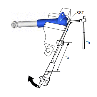
| *a | Torque Wrench Fulcrum Length |
| *b | Hold |
 | Turn |
2. INSTALL REAR SHOCK ABSORBER CAP
(a) Install the rear shock absorber cap to the rear shock absorber assembly.
3. TEMPORARILY INSTALL REAR SHOCK ABSORBER ASSEMBLY
| (a) Temporarily install the rear shock absorber assembly to the rear axle carrier sub-assembly with the nut and plate washer. NOTICE: Hold the rear axle carrier pin while rotating the nut. |
|
4. STABILIZE SUSPENSION
(a) Using a jack and a wooden block, apply load to the suspension so that the rear No. 2 suspension arm assembly is positioned as shown in the illustration.
Standard Length (A):
8.6 mm (0.339 in.)
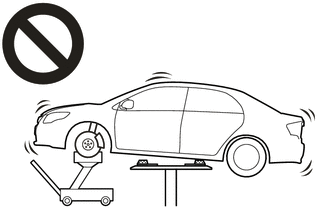
- Do not raise the jack up too high.
- The vehicle could fall, resulting in a serious accident.
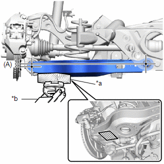
| *a | Wooden Block |
| *b | Jack |
 | Wooden Block Placement Location |
NOTICE:
- When jacking up the rear No. 2 suspension arm assembly, be sure to jack it up slowly.
- Make sure to perform this operation with the vehicle kept as low as possible.
5. TEMPORARILY INSTALL REAR UPPER CONTROL ARM ASSEMBLY
(a) Install the rear upper control arm assembly to the rear axle carrier sub-assembly with the bolt and nut.
Torque:
73 N·m {744 kgf·cm, 54 ft·lbf}
NOTICE:
- Insert the bolt with the threaded end facing the rear of the vehicle.
- Tighten the bolt with the nut secured.
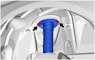
6. CONNECT REAR SHOCK ABSORBER ASSEMBLY
| (a) Connect the rear shock absorber assembly to the vehicle body with the 2 bolts. Torque: 60 N·m {612 kgf·cm, 44 ft·lbf} NOTICE: Temporarily tighten bolt (A) and then fully tighten the 2 bolts in the order of (B) and (A). |
|
7. FULLY TIGHTEN REAR SHOCK ABSORBER ASSEMBLY
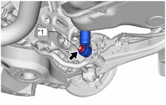
(a) Using a ball joint lock nut wrench fully tighten the rear shock absorber assembly with the nut.
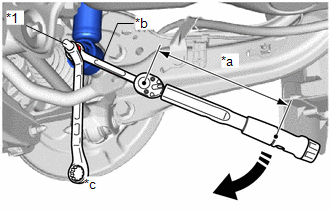
| *1 | Rear Axle Carrier Pin |
| *a | Torque Wrench Fulcrum Length |
| *b | Ball Joint Lock Nut Wrench |
| *c | Hold |
 | Turn |
Torque:
Specified tightening torque :
135 N·m {1377 kgf·cm, 100 ft·lbf}
NOTICE:
Hold the rear axle carrier pin while rotating the nut.
HINT:
-
Calculate the torque wrench reading when changing the fulcrum length of the torque wrench.
Click here

-
When using a ball joint lock nut wrench (fulcrum length of 149.75 mm (5.90 in.)) + torque wrench (fulcrum length of 400 mm (1.31 ft.)):
98.2 N*m (1001 kgf*cm, 72 ft.*lbf)
8. INSTALL REAR STABILIZER LINK ASSEMBLY
Click here

9. INSTALL REAR WHEEL
Click here

10. INSPECT AND ADJUST REAR WHEEL ALIGNMENT
Click here

 Inspection
INSPECTION PROCEDURE 1. INSPECT REAR SHOCK ABSORBER ASSEMBLY (a) Compress and extend the rear shock absorber rod 4 times or more. Standard: When compressed and extended at a constant speed, the stroke of the shock absorber rod is smooth with no abnormal resistance or sounds...
 Disposal
DISPOSAL PROCEDURE 1. DISPOSE OF REAR SHOCK ABSORBER ASSEMBLY (a) Extend the piston rod and secure the rear shock absorber assembly at an angle in a vise...
Other information:
Toyota Yaris XP210 (2020-2026) Owner's Manual: Height Adjustment
Adjust the head restraint so that the center is even with the top of the passenger’s ears. To raise a head restraint, pull it up to the desired position. To lower the head restraint, press the stop-catch release, then push the head restraint down...
Toyota Yaris XP210 (2020-2026) Reapir and Service Manual: Speed Sensor
ComponentsCOMPONENTS ILLUSTRATION *1 TRANSMISSION REVOLUTION SENSOR *2 O-RING *3 NO. 1 ENGINE UNDER COVER ASSEMBLY - - N*m (kgf*cm, ft.*lbf): Specified torque ● Non-reusable part Toyota Genuine Adhesive 1324, Three Bond 1324 or equivalent Gear oil ★ Precoated part - - RemovalREMOVAL PROCEDURE 1...
Categories
- Manuals Home
- Toyota Yaris Owners Manual
- Toyota Yaris Service Manual
- Headlights
- Opening and Closing the Liftgate/Trunk Lid
- To Set Speed
- New on site
- Most important about car
Liftgate/Trunk Lid
WARNING
Never allow a person to ride in the luggage compartment/trunk
Allowing a person to ride in the luggage compartment/trunk is dangerous. The person in the luggage compartment/trunk could be seriously injured or killed during sudden braking or a collision.
Do not drive with the liftgate/trunk lid open